Sunday, June 05, 2011

Okay, I'm opening the floodgates on writing up pending and future projects, until the point at which I've actually accomplished something and can write about it in retrospect. There's light at the end of the tunnel in regards to repair content, only time will tell..


In the last few months I've returned attention to the MIDI realm, instrumentation I've ignored to varying degrees since roughly 2004-5. In the intervening era my primary sound focus has been free form walls of electrical drone and noise, exploiting a fair amount of old tube electronics and manually operated gear in my work.
Bridging these two entirely separate domains has been a kernel I've been quietly chewing on for the duration. Today's instrument under consideration is the IVL 7000 mark 2 Pitchrider, a guitar to MIDI interface from the earlier half of the 1980s.


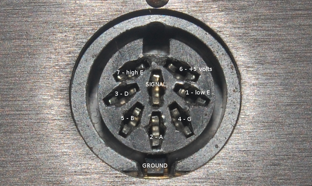
Here is, so far as I have been able to gather, the pin configuration of the 8 pin DIP input jack. This is far easier to see blown up...


Looks like a CD4051BE on each input channel, note the differing resistor stacks. Two of each channels feed a single P8031AH.

Since the CD4051BE purports to tolerate 20v P-P analog or 3-20V digital input, I'm not too concerned over feeding this thing line level in lieu of a standard guitar pickup level.


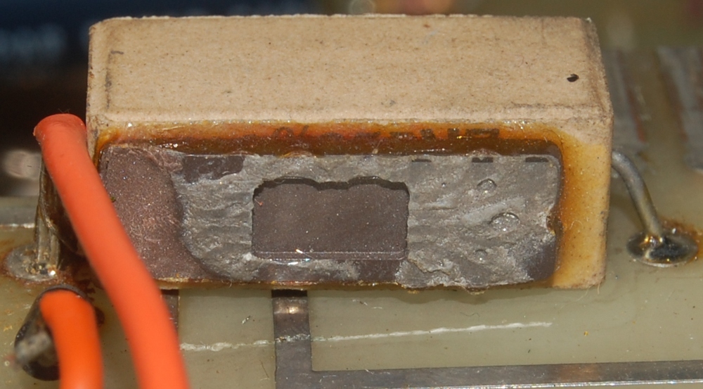
The patch backup battery is a CR2032 in a battery holder, absolutely dreamy compared to the internal backup batteries I'm use to seeing.

So the primary idea here is to translate (6x) signal frequencies into MIDI note data out, paving a path from raw sound to sequence data. Having no manual to reference I can only speculate what sort of MIDI data is supported; I'm hoping that each string input can be assigned a different MIDI channel output, and that signal amplitude will output as channel pressure. Since this is a pretty early device I'm not losing myself to optimism.

Friday, June 03, 2011

Another broken EC-Apparatus high voltage power supply!


The 'stickers' up top say "OK to use 8/25/94" and "DEAD 2/3/97". Took it 14 years to rotate into the scrap pile. The AC cord has been cut. I understand the motivation to cut power cords; it remains annoying.


On cracking the shell, this was the first sight to greet me.


I must admit, I'm having a little difficulty identifying this part. Initially it struck me as a wirewound resistor, but the remains don't exhibit the centralized burn characteristics I'd expect to see from a resistor. Additionally, this part appears to have let loose in a rather prompt manner as opposed to a slow and steady heat build up.

Then there is the ochre build up at center band, which appears to be an original compound as opposed to corrosion products. Electrolyte perhaps? Yet the plate structure, if this is a cap, seems wrong to me, and an electrolytic cap of this dimension sitting on a ladder in the filtering section of a 2000 volt power supply makes no sense either.


Whatever it was, it clearly was not up to the task it was asked to do.


The unit over-all looks pretty service friendly, just peeking above the stack of 47u 450v is a blue backplane connector which allowed removal of the board containing most of the sophisticated circuitry.


Of course, that circuit board offers a mystery of its own.


I should give a big fat sandfilled power resistor a shot in lieu of a 3000-3500 ppm/K tempco on a supermatched pair! That would probably cause a quiver or two in the synthesizer community.

My initial response to this structure was, as is known in the internet parlance, WTF?!

But wait, it gets better:


This is apparently the stock part having failed.

As usual, once the amusement has died down a bit, I stopped associating this structure with a similarly built (though altogether different) structure, and reason that the 16 pin DIP package may not be an IC, but a thermistor housed in a DIP package as part of the current regulation circuit.

I remain unsure. Cool enclosure though, perhaps I will have a go at repurposing it to house a supply that offers a more immediately useful range of voltages, eventually.

Thursday, June 02, 2011

The winter is playing hard to let go, seems my progress (and therefore worthwhile update) is mired as well. So it's time for more scenery.


This thing was salvaged from a decommissioned heap at a local facility. I don't know if it's the ink marker or the metal work that screams home-brew louder, probably the ink labelling. That said, the empty slot cut in the panel is a serious weak point, and I've taken to handling this gingerly as it does exhibit flex.


Flexible framework and iron do not make for an ideal pairing.

Here the sense of home-brew punctuates many nuances of this build; take the size of that fuse and the gauge of wire connected as example. This piece is almost inspiration for one of those find 10 things wrong with this picture puzzles, but to really do that right I'd want to stick Waldo in there somewhere and I'm sure there's some IP protocol prohibiting such behaviour. Such is the world as has been built.


This was the puzzler for me. I spent a few days just glancing at it in passing, subconsciously chewing on it (maybe, the subconscious continues to forge its own itinerary thank you very much). Until this morning when I grabbed it for photographic purpose and noticed the inlet on the underside.


Why, I do believe this a vacuum operated switch. A rather sensitive one from the size of it.. While it would appear that changing out or adjusting the spring tension will manipulate response curves I wonder if this will reliably cover the range of operation I would want to deploy in a vacuum table.

Since I HIGHLY doubt I will redeploy this unit to do whatever it was designed to, I'll probably pull that plunger assembly and find out, when I get to that phase in the CNC project.