Showing posts with label selenium. Show all posts

Wednesday, December 28, 2011

DeVry. I just spent a few minutes of study trying to craft a neat time-line fashion historical interconnect between this amplifier and the DeVry technical institute. I wound up digging up ties to Lee de Forest and Bell & Howell. They are all connected in some manner. I'll leave it at that. It's just too convoluted a maze to touch upon here, and I'd like to flow some solder sometime today. Lee de Forest is an interesting character steeped in early electronics design lawsuits, let me kick this off with a quote:
"So I repeat that while theoretically and technically television may be feasible, yet commercially and financially I consider it an impossibility; a development of which we need not waste little time in dreaming." – 1926

Had they listened, what would we be doing today?
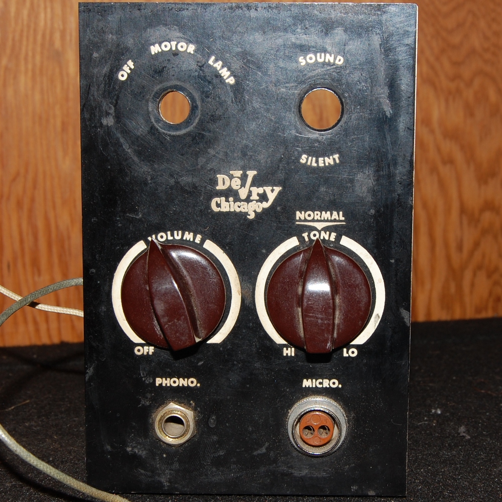
To sum it up: Hot chassis film projector amplifier.

The enclosure really speaks to my growing fascination with modular synthesis. Observe that the selenium wafer stack is bypassed with a silicon rectifier. The silicon rectifier exhibits a much lower internal resistance of roughly 0.6 volt forward drop than the selenium wafer stack, which exhibits roughly one volt drop per wafer - almost ten times as much resistance in its conductive cycle. Therefore, during the conduction cycle the electricity will follow the path of least resistance and bypass the selenium stack. However, each selenium wafer only withstands roughly 20-25 PIV, which is why they are stacked to provide a working voltage to begin with. By not removing the selenium stack from the circuit, its 100-125 volt PIV rating still stands during the non-conductive phase of the AC cycle, which, may I remind you, is non-isolated 120 volt mains.

In short, bypassing in this manner is a terrible idea.
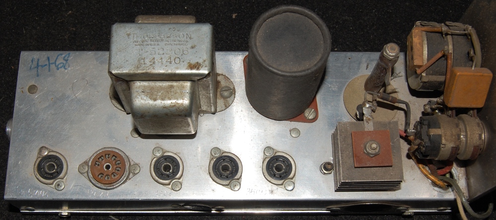
Engraved by hand on the chassis at the tube sockets are the following designations from left to right: 12AU6, 12AX7, 35C5 and between the two sockets at the right 35C5. The right-most socket is wired differently, and during a few moments in which I had blocked the memory of the solid state rectifier from my mind, I considered this an error until I did a little more hunting.

Discovering pictures of a similar DeVry projector at auction produced the layout legend above.

Another note. I won't tear this one up, sort of speaks for itself.

Gut shot! Finally some guts. One of these weeks or months I'll dispel with the commentary and just cut to the chase and post innards. I owe it to the internet.

Thordarson transformers. This company has been going since 1895, keep the dream alive. I personally feel that the creed from 1937 far outweighs their current motto, steeped as it is in the way of things...

For all the shit I've heaped on selenium, the rectifier stacks sure are pretty.

I'll post a proper retrofit eventually. I realize my content is flighty, best to just roll with it.

Wednesday, October 20, 2010

Can I make a joke along the lines of: if it's Federal, it's probably not good for you? I guess I just did. On that note, did you know that the archaic form of the word federal is foederal? I suppose that label was deemed a bit too transparent (cue laugh track). But, I digress, I'm not interested in talking about commonly accepted popularity contests or congregations of self important assbags, I'm more interested in rectifiers at the moment.


Here's a close-up of the selenium sandwich stack in a Navy ME-6D/U electronic multimeter (which will likely be covered in a future installation). Ease of identification is selenium's greatest attribute, it can typically be spotted in well under a minute of having cracked the case. The component pictured above is a less common version without the oversize heatsink fins. My philosophy is to change selenium out when I see it. You can read about the failure modes elsewhere on the net, here's a fine write-up: http://yarchive.net/electr/selenium_rectifiers.html. This is the rectifier block in schematic:


And, extrapolating from that, the electrical orientation of diodes in the stack:


In terms of out with the old and in with the new, this cannot be easier to wire; the main concern is going to be introducing some sort of framework that will avoid a free form rat's nest sculpture that's rectifying the B+ voltage (I'll be sure and photograph this section when I post an update on this unit).

In terms of electrical characteristics, selenium and silicon are not identical, and depending on the installation, a low value high wattage resistor might be beneficial in terms of nudging your B+ down a bit. Also keep in mind that average wall voltage has crept up over the past 50 years (I think evidence of selenium in the power supply typically dates the unit to that age at least) so the combination of higher AC mains and reduced internal resistance at the power supply might place undue stress on the circuit. A bucking transformer at the power cord is generally a good idea (even with tube recitification). http://www.philcoradio.com/phpBB2/viewtopic.php?f=11&t=2247

Regarding the selenium pull jobs, I have the sick notion of dropping them into ring modulators. Owing to the greater forward voltage drop (read as lower efficiency) I expect I'll need to build boosters on all three legs of the circuit. We'll see what shakes loose on that front.