Saturday, January 22, 2011

I hope you like yellow.


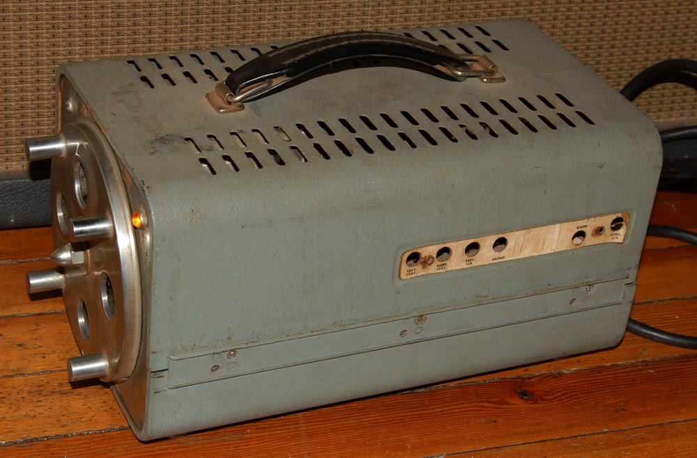
Huge round of thanks to BLOODSON DRIFTER for dropping this CONTROL CONSOLE case on me. This this is full of its original parts and a bunch of circuit boards from an Elka organ that I'll cover some other day.


Part of MC-1 MAG. COMP. CAL. SET, "modified", which at this point is absolutely accurate. Built by Sperry Rand to Mil Spec C-26524, which I think has to do with the ruggedization of the case. This appears to have been surveyor equipment.


Gutted is a form of modification. The panel as pictured is downside up from original positioning, evidently the original purpose was facilitated by having the lid swing out toward the operator. My thinking is that this case is appropriate for a synthesizer build, but only with the panel positioned as seen. That's for another day though (eh, it'll take a bit longer than that), time to dig through the contents and see what's here.


Most of the stacked switches bear the manufacturing mark of "CINEMA PLANT/HI-Q DIV", a date code sitting somewhere in the latter half of 1965 and a part number. From left to right the part numbers are: 65054, 65062, 65059, 65061, 65060 & 65060.


This frame illustrates the construction of the switch/attenuator with a little more clarity.


Part numbers: (ASSY) 2587148, (ASSY) 2587148, (ASSY) 2587201 & (ASSY) 2587201. The two assemblies on the left carry transformers, the two on the right are mainly comprised of a "MOTOR GENERATOR" coupled to a multi-turn pot through a series of gears that substantially step down motor RPM. The motor appears to be set up for 33 volts at 400 hz AC, 28oz inch at 9500 RPM; the generator providing 26 volts. It'll take a pretty low Z signal for the 2500 ohm potentiometer to deliver acceptable results as a VCA (A standing for Attenuator). Perhaps VCP would be a better term?


Part numbers: (ASSY) 2587953 & 65063 (the part pictured above in the close up). Assembly on the left delivers the visual indicators of Degrees & Minutes and carries a multipin connector for interfacing to other equipment. That assembly occupied the large rectangular hole in the panel, for which I have other ideas.


Part numbers: (ASSY) 2587200, (ASSY) 2587200, 65059 & K650937 (Branded "TECHLAB"). It would seem reasonable that there would be active electronics in this thing at one point or another. A few GE transistors collared into place (preventing positive ID), some decent caps and what appear to be more transformers.

Current thinking in respect to this enclosure and panel is building some fundamental tube synthesizer circuits onto the panel (probably a mix of classic circuits and some Barbour circuits as found at CGS), and utilizing the generous space on the interior of the case for a solid power supply that will support numerous outboard modules as well. Just brainstorming at this point in time.

Thursday, January 20, 2011

Have run into a bit of a back and forth in terms of getting my transport sorted.


These parts are so close as to not actually work as designed. This brass nut was sent as a replacement for a mis-picked Delrin plastic nut (originally shipped in the larger size of the other screws). I'd like to employ the clearly higher quality metal part, but need to make them work together.


My hopes are that the out of whack thread starting at the point it is turned down are what is prohibiting me from threading the nut. I'll file those bent ridges down without side loading and hope that allows freedom of movement.


It's either that or tapping out the nut.

Tuesday, January 18, 2011

Received my ON-Semi MJ21195/96 power transistors for the Soundcraftsmen power amplifier late last week and slapped them in over the weekend. In a wholly unscientific manner I opted on the MJ21195/96 because the response curves tapered in a gradual manner and the ramp up to roughly the 50% current output appeared peppier. Plus they were cheaper, by 57 cents each. If the amp sounds like shit when I'm done, exploring the other output devices is within my capabilities.

That would, naturally, only happen after a recap and some other tweaking the good people at audiokarma.org have spoken of.


This, and a pair of pliers to grab and twist the shaft, is how I reached the rear screws without tearing this thing completely down.


As I wrote a while back, the rebranded TO-3 transistors were less than informative in regards to determining which of the 2SB554/2SD424 pair carried which cryptic alpha-numeric stamp. Direct measurement to determine the orientation of "diodes" on surviving devices was the simplest route to identification, here we see the unobtanium "5A" PNP (2SB554) being replaced with current production devices.

Replacement surgery went well, next up looks to be replacing the differential pair to shed some DC offset on the outputs, but before I go that far I aim to secure a copy of the service literature on this amp to assist in avoiding any pitfalls. Why yes, I probably should have had that from the beginning.

Sunday, January 16, 2011

I washed the upper PCB of the ART DR-X effects unit today. This process consisted of the following tools:


One used toothbrush (largely defunkified through prior use with isopropyl alcohol), one 8x10 photo developing tray, one gallon of distilled water (of which approximately one pint was used here), an air compressor and a heat gun.

I pulled the following shot from the previous write-up:


Since chemistry isn't my strong point, I can only guess that the white chemical growth at the legs of the pins is caustic potash. Therefore, I reason that a mild detergent is probably not required, since the caustic nature of the build up is going to provide more "cleaning" power than I probably need to begin with.


I poured enough distilled water to just cover the top of the ICs, and before agitation a considerable amount of the white build up dissolved. After 30-40 seconds with the brush, I hit the PCB with compressed air to disperse most of the water, then followed up with the heat gun. In order to avoid overheating the PCB, I held it by hand while distributing heat (which was a huge motivator to keep that gun moving). The idea behind the heat gun is to encourage evaporation of moisture remaining after the compressed air.

Something had been bothering me about the source of the saponification; in the past when I've seen this build up it has been localized (or at least centered around) a decomposing battery or electrolytic capacitor. This was distributed more or less evenly across the entire PCB, moreover the back-up battery and capacitors did not exhibit any of the build up.


An aspect of metallurgy is that dissimilar materials will often facilitate corrosion at contact points. In comparing before and after wash pictures, I can't help but notice that a good portion of the build up is centered on joints that were not completely filled in the soldering process.


A closer inspection of the lower, largely digital board reinforces the theory that the poor infill is, if not the root source of the failure, at least largely contributing to the problem. By the mid to late 1990s I recall that ART effects from the earlier part of the decade had gained a reputation of unreliability, which leads me to wonder if the chemical build-up around the legs, which certainly may have been allowing functionally disruptive crosstalk, wasn't isolated to this unit alone.

Perhaps I'll trip over some similar era non-functional ART units upon which to test this theory.

I'll need to grab a larger tray to wash that board though, so this process remains in a state of limbo.

Wednesday, January 12, 2011

I keep thinking back to a television episode I watched as a kid in which a group of colonists stranded on another planet were forced to repair and reuse everything in order to survive. When the relief ship arrived to haul everyone back to earth the primary mister fixit urged everyone to stay behind, as his importance within the community would essentially evaporate once repairs were no longer crucial to survival. He elected to stay behind and everyone else boarded the return ship; it was not until they were riding atop the trailing flame of their rockets that he changed his mind, too late.


We've gone from largely hand built constructions that demand great skill to achieve precision to hand assembled constructions built from premanufactured components to altogether premanufactured constructions. Unrepairable in the climate of replacement, each generation relaxing the criteria of skill needed to maintain operation.


Having largely abandoned constructions built by hand, our remaining frontiers are burdened with the inclusion of heavy industry. Furthermore, disposable culture has tied industry up with the regurgitation of every day objects that could be scratch built or at the very least repaired and maintained from existing stockpiles. A purist will point out that these objects (such as audio amplifiers, engines, computing and communications machines) could be eliminated completely, without negating survival, personal strength or evolution. This, however, places demands upon the masses to shoulder a burden that has thus far been alleviated through the seeming perpetual output of industry.


Of course, it was pointed out some time ago that for every action there is an equal and opposite reaction. Unless something is cyclical and self contained, perpetuation is highly improbable. Which brings me to the root motivation I have for my fascination of repair and with archaic technology in general.


Early technology is built upon human endeavor, it is attainable with simple tools. You and I can build this. Easily understood, should we work at understanding it. The fixation with application often overlooks fundamental construction. The construction that civilization has implemented to shore up its ever reaching (though largely directionless) plateau has become many generations removed from human creation. Hopefully if we awake one day to find ourselves on a depleted plain with limited tools and resources, we'll retain enough know how to forge survival.

Monday, January 10, 2011

It's high time to grok the guts of this old tube television camera.


I believe this is a Sylvania VRF 400, unfortunately any and all exterior labels were long gone by the time I pulled this out of a junk heap (or, if you prefer a little more accuracy, off the shelf at a local reuse/recycling center). I have yet to swab the filth off of the components; and as such am having a hard time zoning in on a familiar date code format, but I think this thing was built in the early 1960s.


I'm fascinated with the notion of actually putting this thing to work, relishing in all the black and white Vidicon artifacts. For my application, precision is far from required.


Underside of the unit is largely dust free, showing off the printed circuit board. To the immediate left is the power supply mounted to a panel that conveniently swings out for access. I love these reminders of technology built with repair in mind, it's a shame that's little more than an echo of a bygone age at this point.


Honestly, I think this unit will require a ground up rebuild to achieve operational status, though I may get adventurous and try it out once the ruptured parts are replaced.


Rather, once I replace the ruptured (and intact) electrolytic capacitors AND update the selinium stacks I may experiment with operation.


Of course, that puts a lot of faith in this wiring.

This camera remains at a lower tier of my priority list. Though I must admit, having contemplated the guts a little it does appear far simpler than I had originally feared.

Sunday, January 09, 2011

It's time to take the plunge into digital. Hailing from an ugly era of electronics: the fuschia script Applied Research & Technology DR-X.


On initial power up all I got was LCD backlighting, no character display or response from buttons. I've seen this symptom occur before in power starved conditions, which is easy enough to troubleshoot with a voltmeter. A day later, before I cracked the case on this unit I wanted to to get a picture of it. Naturally, that symptom went away and gibberish replaced it.


This hints at failure of back-up battery to me, probably coupled with power delivery issues that may be as easy a fix as redressing the interior wiring connectors. One thing has always bugged me about these gibberish displays, that I cannot recreate the character strings on an operational unit.


Circa 1990 through hole digital construction. Judging from the chipset the upper PCB looks to support the analog signal path while the larger board is populated with digital ICs.


A closer look at the PCB reveals what appears to be caustic potash (potassium hydroxide / electrolyte) corrosion simulating snow drifts at the legs of the ICs, indicating that this unit needs a little more help than replacing the backup battery and exercising the ribbon cables. Thankfully this unit is disassembled with ease, so washing the PCB will be a snap.

After which it's probably looking at a re-cap.

Friday, January 07, 2011

Stumbled on a cut-away for a precision multi turn pot.


There's a car that rides in the gap between the adjacent coils of the wire wound resistive element, I believe it houses or provides alignment for the wiper.

In other news, the Peavey Mark IV was put to test on a speaker load. After a minute or so of fantastically textured white noise it passed signal well. The floor noise diminished with use, isolating the cause of the noise is on my to do list.

Thursday, January 06, 2011

Inching forward with the CNC project, my screws and some hardware have arrived.


Here's a quick mock-up of my X axis, well, hardly a mock-up, but I digress. Framework and data handling aside, these are the important parts.

X axis is to ride on THK linear bearings, driven by a Pacific Scientific Powermax II stacked stepper turning a screw, powered through a GeckoDrive G201X which will receive commands ala dedicated desktop PC running Ubuntu/EMC2. Having all these components laid out in front of me means I really need to address the power supply sooner than later (now).


Front and center sits 112 pounds of power supply, waiting for me to lug it to the bench.


It's only after executing that little juggling operation that I remember this is the unit with a faulty breaker on the DC side and what I'm really after is the 107 pound power supply that was sitting next to it.


After a brief inspection confirming that the power transformer is strapped for 120 volts and nothing is visibly leaking, bulging or dead inside the case, I fire it up. The hum of operation borders on a buzz, but no smoke or sparks thus far... good.


There's a standard cassette tape at upper right for scale.

There's a point of concern with this PSU, the DC breaker. I've gathered that it's inadvisable to to switch the DC side of the power at the drivers, as they will face back EMF from the motors which can burn them up, setting me back replacement costs on up to four G201X, which isn't something I'm interested in.

The supplies are also tailored to battery charging, which has a different set of operational parameters than driving motors. My Y axis will have two motors working in hard sync to move each leg of the gantry, the two stacks of each motor are going to be wired in parallel, offering a path rated at 7 amps per motor. So the last thing I want is some battery configured current sniffer to crowbar output voltage when I most need it.

In short, I came to the realization last night that my best tactic is to gut the logic/regulator portion of the power supply, reconfiguring it into a primitive rectified DC beast, which, as I understand it, is best for this brute force application to begin with. I guess I could have stayed with the heavier supply after all.

Wednesday, January 05, 2011

"No highs, no lows, must be BOSE", I think I've lost track of how many times I've seen that statement bandied about. Yes, I am aware that this specific speaker system requires frequency compensation to achieve a full range of sound. No, I haven't experienced this full range wonder first hand, but have a fair idea of what it sounds like.


See, I've experienced the rich, almost tangible ambience that a well amplified live act can deliver to a well balanced room. In my (again, as yet inexperienced) mind, the hubbub surrounding the BOSE debate is that the BOSE sound embraces live experience (not to be confused with reality). They purportedly sound big and full, and looking at the undressed baffle, I can bridge the disparity between a full stack of eight 12 inch guitar speakers across a hall and these eight 4 inch drivers right in front of my face pretty easily.

Besides, I'm absolutely not interested in using these as say, studio monitors; rather, I'd like to deploy these epic characteristics that some people defend with such gusto as a recording stack for guitar, etc. No harm in investigating the phenomenon.


However, in doing some preliminary research I've come across two widely agreed upon points.
1) Evidently BOSE doesn't believe in publishing curves or specs on their wares.
2) These seem to be geared toward high power applications, hinting at horrible efficiency.
The low efficiency angle may render my original idea of making a nice compact stack with the Princeton on top into mulch.

After thinking on it for a bit, I've decided the efficiency thing is not a dream killer, as I can simply deploy a higher power tube amp to drive these at lower recording friendly volumes.


Of course, I'm bound to discover some obstacle to my quest for determining if these things can sound useful at all. I observed a few drivers were resting loose in the case, so naturally I take a peek inside. That's about as shifted as a magnet can get.


These two parts are in love. I didn't exert a lot of brute force in trying to free these, as magnets are jumpy and I'd just as soon retain the voice coil that appears to have escaped unscathed. I'm guessing these were dropped, the basket to magnet joint failed - dropping the magnet, and whoever discovered this on inspection placed the magnet as seen to prevent further damage. In the meantime, remaining adhesive qualities of the cement have frozen the moment in time.

So my plan of just plugging one in and seeing how it sounds has been replaced with tearing one apart, making sure all the drivers are intact and operational (hopefully failure has been isolated to one cabinet), and doing what I can for the other one in time. Fortunately I have drivers awaiting refoam that will drop in, as I'm not tooled up for the precision alignment to reglue the basket to the magnet.

Tuesday, January 04, 2011

I've depleted my stash of basket case amplifiers on hand, so it's time to crack the case on that Peavey 260. Don't worry, there are plenty of basket case amplifiers and so forth that will be looked at in the future, I just have to dig them out.


Access to amplifier transistors is about as easy as it gets. My original hunch on this amp, that carried 39 volts DC on the signal pin of the output jack, was that of a failed power transistor. These all tested good, so my suspicion has been downgraded to failed driver pushing the output into saturation or good old fashioned funkiness with the connections.


These sockets may have to go. I'm weighing out my abilities to polish/inspect the connector surface, while my mind keeps interjecting "remove and replace". Honestly, circuit analysis while charged seems pointless while these sockets are cradling the pins of the output devices. I should also mention that the pins on the TO3 transistors are also less than pristine, almost as if something has been electrochemically corroding them.


The power supply capacitors are clearly in need of replacement, physical distortions are evident.


I also don't approve of the mains ground termination, pictured here tying in with the sleeve of a speaker output jack. This makes for a completely mechanical joint, relying on the nut that holds the jack in place to complete ground. I'm guessing, if you're reading this, that you are familiar with these nuts of which I speak. They wouldn't be my first choice for a safety feature, but this isn't the work of Peavey, it is a retrofit to three prong from the OE two prong power cable. Better than nothing I guess, I'll still change it to satisfy my standards.

Monday, January 03, 2011

Well, discouraged by the relative success of yesterday I plucked an ugly one from the pile, a Kasino U200P Concert powered mixer.


When exhumed from the bad amp room this one was just the chassis, I made the connection to Kustom (kind of hard not to) and imagined this in tuck & roll. Doing a quick google search on the Kasino line, I quickly learned that they were not tuck & roll, which further led to the realization that I had the tolex enclosure on hand already.


Initial inspection got this far, so, I've got some work to do before this thing has the opportunity to entertain me with sparks. I'm bummed that this two conductor power cable is long gone, as I like to turn them into speaker cables.


In the event shearing off the power cable at the chassis isn't deterrent enough, the hot line to the switch has also been plucked.


Here's some gut-shot, lower left is a channel input board. Most of the component date codes are situated in the middle of 1971.


Output driver board on back over output devices hanging off the bottom; I'm guessing the PCB on the bottom panel at lower left is channel summing and reverb support.


Surface rust is evident, indicating the condition of interconnects may be in need of attention.


Nothing says class like embossed label plates.

Sunday, January 02, 2011

Next Peavey up is a Mark IV 400BH solid state bass head.


Initial inspection indicates this unit has been harvested for knobs, or a shade tree technician removed the knobs on disassembly and didn't return them to the device when put back together. The result is the same: the knobs are gone forever, perhaps floating in a rift in the space/time continuum hanging out with pre-war change and 45 rounds in Elvis Presley's pocket; or maybe resisting decay somewhere on a garbage barge. It's good practice to completely reassemble something if it's going to face any length of time away from the bench.

I digress, plucked knobs says "parts unit" to me, lending weight to the notion that this amp is a goner. Goody!

Inspection also indicates a bent slider shaft, which proved easy enough to bend back into shape, and a stressed power cable.


The power cable is cinched tightly around the heat sink, which doesn't do this failing cable insulation at the chassis clamp any good. I don't see any frayed wires though, so let's plug it in and see what happens!

Amplifier powers on and stays on.

DC voltage reading at speaker output is in the 200 millivolt range. Not exceptional, but it also hasn't had a chance to temperature stabilize; the point is there isn't a DC voltage in the speaker cooking range, yet there's obviously power of some sort.

Next step, since I already have the meter plugged into the power output jack and my o-scope is not at hand, is to set the meter at the low end of AC range and look at floor noise (that occurs within the time base window of my DMM). I naturally assume that this will not read hiss and thermal noise, but will read the frequency range of hum and buzz coming from the power supply. Meter indicates low millivolt range of AC voltage on output.

Since I'm doing this in the relative warmth and comfort of the apartment, I'm not at liberty to plug in and ramp up 200 watts of power into a cabinet, and the scope and dummy loads are elsewhere. So, the next step just confirms signal path and certain elements of operation, it is also a solid state only procedure, as the mega-ohm range on the input of the DMM basically amounts to no load at all...

With voltmeter plugged into the speaker output jack and set to an AC voltage range that supports 30 VAC, I plugged an instrument cable in the high gain jack and touched the tip without grounding myself to the shaft. ~10 volts AC appeared at the output. The low gain jack produces roughly 25% of output voltage that the high gain jack does.

While producing signal in this manner, I turn the volume controls, they seem to operate as one would expect. The limiter indicator also fires once output voltage hits 27 volts AC, though output voltage ranged to around the 33 VAC mark.

All of these steps occurred well within the space of 5 minutes. So, without having actually tested the amplifier section under load the amp passes signal and does not produce copious DC on the output, so the next step is to plug it in and observe its operation in actual use. That's for another day.

Fix list so far on this unit: locate suitable knobs (knurled 0.185" diameter) and release the power cable to pull it into the chassis by about half an inch.

Saturday, January 01, 2011

I'm going to outline my initial steps in assessing the state of amplifiers in an unknown but assumed to be malfunctioning condition. I'll attempt to be thorough as I dig through a small heap of amps, but it's very possible I'll overlook one of those obvious to me steps that has become a thing of second nature. Long story short, this is a document of my (largely self taught) approach, and shouldn't be treated as an all inclusive instructional document.

First up is a Peavey 260 series amplified mixer, visual inspection reveals that someone evidently did not like the Peavey logo and blotted it out with an indelible marker or polishing compound of some sort. The logo remains intact, so it should prove easy to return to its original beauty with something like a silver paint pen. Visual inspection also confirms that the power cable appears intact and stress free, so let's plug it in.

Amplifier powers on and stays on, so far so good.

Before putting a load on it of any sort I'll probe the speaker output for abnormal voltage.


Speaker output is delivering over 39 volts DC to whatever is plugged into it.

This unit is a speaker killer, and illustrates why unknown amplifiers shouldn't be plugged into speakers prior to a brief preliminary inspection.

My hunch is shorted output devices shunting rail voltage to speaker jack. This one is heading for the bench.