Monday, May 16, 2011

Let's have a look at a couple drum machine sections from the organ donor pile.


Here's the drum accompaniment section from the Wurlitzer 4373. This one stands out as being a contender for rehousing due to its compact nature. Pattern selection is achieved via rocker switch as opposed to radio buttons, so stacking up genres does not require a deft hand.

In looking at the neatly stacked PCBs at left, I believe we've got analog sounds at top and digital logic amidst the spread of ICs on the lower PCB. I dig the simple user interface on this thing, visualizing it in a dark wooden enclosure is a snap.


Here are the auto accompaniment modules for a (near as I can figure) 1969 Thomas Organ, each self contained in a stapled shut press-board enclosure.


The "Playmate" was less than forthcoming with offering up a top side gut shot, what with the staples and all, but I'm going to guess that this perspective is actually the more interesting of the two anyway. I believe the circuit board at left contains the sound module portion of things, based on the type of wire connecting. Looks like four primary sounds that are mixed into a drumset (noise and high-mid-low oscillators would be my guess).

The board at right interfaces with the radio button strip, which would probably be ousted for discrete switching in the event I get around to rehousing this unit too. This would be my candidate for pattern source.

They don't make them like that any more, who needs connectors interfacing between the circuits anyway?


And who needs a backing band when they can use one of these? The Band Box. I like this enclosure framework a lot, too bad they wrapped it in cardboard. Potential remains..

My contemplative abilities have sort of abandoned me on this one. I don't see a multi-pattern sequencer and sound source here, so logically I'm leaning toward this being a pattern sequencer. That said, as I recall organs operate via a bank of manually operated switches passing oscillator output, and being that there was not a bank of relays a simple sequencer would meet with difficulty tapping into the oscillator banks (which so far as I know do not respond to CV for instruction). When I was tearing this one down I was in more of an "I need some space" instead of an "I wonder how this works" frame of mind, more's the pity.

A heap of RCA transistors in a (presumably) functional black box. There, I feel better.

Friday, May 13, 2011

The path of progress.


Cut some passages in the heap of junk yesterday, more to come. The attempt at a bench in the laundry area hasn't met with the success I had hoped for, so it's back to making this space viable.


Looooong way to go, but being able to access all the corners is a good step.


Floor! It's there. Really. Behind some of that stuff.

I also seemed to have been focusing on a plane either nearer or farther from the subject matter, so blowing those shots up is bound to disappoint. HAH!

Certainly looks the part of the hoarder, but incoming has trickled down to almost nothing. One pending/maybe sort of acquisition, then it will only be the truly rare finds of the sort that find me to add into the pile.

Tuesday, May 10, 2011

Took part in an organ grinding party last weekend.


Wurlitzer 4373, the organ donor.


Not really a whole lot to it, the disassembly that is. Most (if not all) console organs were built by hand, which is a boon to disassembly as it can be achieved with simple hand tools and minimal destruction. Pictured above are some sections of the Orbit synthesizer that was being extracted prior to tossing the rest into a rendering pot.


I picked up most of the remaining mash, including woodwork which was promptly flattened into as close an approximation of sheet stock as I could muster with minimal fuss. Included in this heap of discrete transistor constructions was the above contained circuit, sealed away from curious fingers. The ICs are marked "X", Google isn't being very helpful regarding coughing up a datasheet. I'm guessing it's a high frequency circuit based on tuning cap and that weave of wire, which probably exhibits just enough capacitance for that shape to be meaningful.


I love looking at this. I'd hate to have to work on it (more than I have to, what with some of these old mixers hanging about) so it's a lot easier to plunder guilt free.

Monday, May 09, 2011

Met with an error screen on my Alesis HR-16B.


A little internet investigation indicates a likelihood that this is due to a failed back-up battery, a Tadiran TL5101. This was built early 1990, so it is reasonable to assume the battery is toast.


The above sentiment applies to the entire family here. I'm going to crack the case on each of these to confirm that the TL5101 package is the same on all, as I really hate having to improvise with batteries when an easier option exists. For what it's worth, there are three available packages of TL5101, and a variety of PCB revisions for the Alesis units.

While I have the trio together it makes sense to do a quick run through of each and earmark attention areas I should address while the case is cracked and I'm changing the battery.

The MMT-8 was a bad amp room unit, so my expectations were low. Powers right up, logic responds without readily apparent glitches and the pad response is very crisp. This must have been in the boneyard due to a misplaced wall wart.

The HR-16 was purchased used in 1998. The pads are in complete need of rework, this unit is almost unusable as is.

The HR-16B was a trade a year or two ago, pads require a firm hand but respond under pressure and the volume and data sliders had been sheared. It also needs a back-up battery.


The axial 1/2AA package is standard across all three examples in my possession. Inorganic.


I had envisioned some level of nuisance in regards to the sliders (mind you, I have not yet narrowed them down to a part number and learned of availability).


Any concern I had regarding remove and replace is unfounded however.


Concern over the Alesis QC is another story, though in their defense this unit has run for over two decades (it could buy beer if it was so inclined) so the unseated IC isn't detrimental, it does however stick out like a sore thumb.


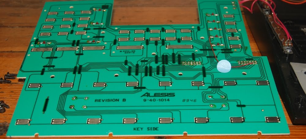
Conductive rubber keypads are, in my opinion, a tool for post warranty failures. Perhaps I have never happened upon the right mix of chemicals to replenish the conductive nature, and I've always been wary about trying a conductive paint for fear of adhesion failure making a huge mess. So it looks like aluminium foil to me. I'll do a bit more research before actually performing this irreversible modification, but if my other option is trying to punch through the PCB traces I'll clad these nipples in foil at the drop of a hat.


Keypad modification sounds a lot more pleasant than fabbing another interface PCB.


Here's where the velocity information comes from, a quartet of piezo discs on the backside of the drum-pad section.

Motherboard time:


MMT-8


HR-16, looks like a Rev. A in referencing the service documents.


HR-16B, service docs indicate this is a Rev. AQ, so I'm going to climb out on a branch and speculate that the revision sticker at lower right refers to software, not hardware.

Wednesday, May 04, 2011

Looking at yesterday's thumbnail format stretch artifacts is like bludgeoning my tired eyes with a dirty sock full of semi-liquid smelly cheese, so I'm going to push the envelope on my quality vs quantity check valve in an attempt to make those blurry images fall off the front page.

Brute force once again takes first chair at the opportunity to fine tune, forgive me, juggling computer code does not represent the satisfaction of hitting my thumb with a hammer.


About two years ago I spied an old tube radio on craigslist for a price I couldn't pass up. It's an old push-pull 813 that has seen better days. Having no intent to invest a large chunk of time to jump through the FCC hoops required to operate on the AM bands, and given the condition of the unit at the moment I'm thinking more along the lines of repurposing the enclosure, and reusing the salvageable parts.


Rats nest wiring.


Dusty 813s and tuning capacitors.

I remain fascinated with the notion of having a go at cloning a Fairchild compressor (well, two, for stereo) and keep being reminded of that fact when I look at this thing.

Tuesday, May 03, 2011

Played a set last night, this seems like as good a time as any to dip into the original intent of these pages, talking about gear (from the on the surface standpoint). I'll also break my established landscape image orientation habit. (well, it appears the stretch involved in retaining my format width makes the nested portrait image look much more low resolution than it actually is, probably won't be doing that again.)


This is my current live set up.

From the top down:
Stereo transistor fuzz
Alesis 3630 compressor
Roland SMX-880
Shure ST 6300 type 2 (2x)
Grass S4 tube pulse generator
Peavey EQ-27

This is what it sounds like:
[view] - live, 27 March, 2011 @ Aminatas by crochambeau

Probably something of an acquired taste.


Here's where the rubber meets the road. There are several feedback loops going on here, some of which are nested in a count the triangles sort of way.

Pulse feeds EQ.
EQ splits output into three feeds, to a line mixer channel and "Aux in" on each 6300.
Each side of the 3630 is fed from "Link B" total summed output from one 6300, the signal is returned to the "Link B" input which bears no manual level control (amplitude being controlled at the 3630)
PA output of the 6300 has a level control, each 6300 feeds one side of the stereo fuzz, which in turn feeds two line mixer channels.
6300 Link A output feeds SMX-880 directly
Each side SMX-880 XLR output feeds channel 1 of the corresponding 6300.
XLR "transmit" output of each 6300 feeds channel 2 of the other.
The image above also shows the 1/4" output of the SMX-880 feeding its own 7/8 channels, but those were spare cables, unplugged to allow connection to the PA system.

Having but a single rolling rack as a live set-up is enjoyable compared to the heap of shit I used to carry, but the low frequency department is not highly represented which is something of a problem in the long run..

Monday, May 02, 2011

Perhaps I should change the running title to "broken stuff" instead of "machine log", especially since most of what I focus on isn't technically machinery in the first place. Nah.


Here's a GenRad 1390a noise generator.


The power switch was already sheared when I bought it, and being a three position rotary wafer it will not be as simple as slapping a SPST in there.


Gutshot.


Here's the heart of the noise generator, a 6D4 in a magnetic field, sort of the tube era equivalent of a lifted collector. Okay, not really a firm parallel there, but work with me here.


I think this unit saw some service, as there are a few thermal stains on the chassis. I'm pretty sure the shake and bake coating on this cap has more to do with a "sticky" shell picking up airborne debris than heat, but the airborne material was probably agitated by the heat and magnetic charge of the powered device to begin with.


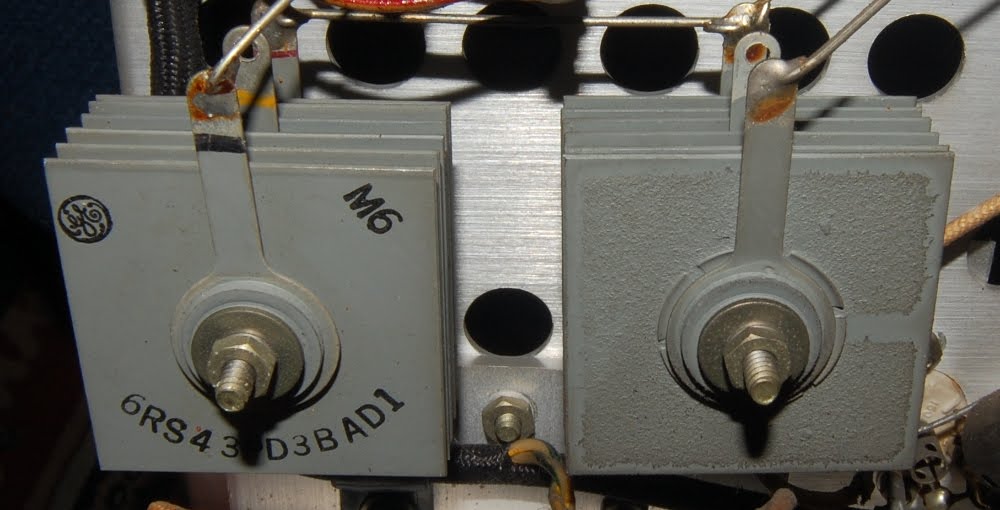
More selenium, which reminds me I have a backlog of simple surgeries to perform with no excuse..

Sunday, May 01, 2011

Mayday! Time to get some progress and self serving industriousness laid out, and resume paving the path to the future.

Forging a bit of progress on the CNC project. Smoothing out nicks and surface irregularities of the structural material through a gentle file hone and fitting the bearings onto the screws as outlined following.


In preparation I stuck the screws in the freezer for the afternoon, and the bearings in an oven (initially at 250 f) for ten minutes. I forget the actual room temperature dimensions, as they were compared at ODD a while back, but it did amount to an interference fit. The hope here was that between thermal expansion and contraction a fit could be made without the necessity of an actual press.


Note the frosty condensation at left offset by the heated metal at right, the metal cylinder was the bearing race "anvil" to alleviate hammer shock from being transmitted through the bearing itself. The first two involved hammering at the coupling end. This wasn't a huge concern as the coupling end is not a super critical precision surface as it will be floating to allow drift from minor misalignments to be taken up at the coupler as opposed to premature wear on the bearing surfaces (no mushrooming occurred).

The second bearing was a bit more resistant to installation, probably due to the cooling of the bearings during the first installation; so the third bearing was heated at 350 for five additional minutes. Additional heat was the key, as the third bearing required no hammering at all.


Installed, ready to move on to structural plotting, based on actual measurements of installed screws.

Sunday, April 24, 2011

And now, for something completely different.

In lieu of fixing things, disassembling stuff or making racket and a mess near the work bench I've been re-familiarizing myself with the Akai MPC 2000xl. This machine was the backbone of essentially all of my audio work from 2000 through 2004 and was rotated into the neglect pile sometime in the window of 2005 due to an interest in less constructed work.

While constructivist (not to be confused with the art movement) leanings return, musical taste and direction has drifted a bit since then. So while a lot of the sounds I had created remain useful, others (primarily in the brass/upper register department) suffer from being overused to my ears or to pulling up short in the quality department. Fresh cymbal sounds became a priority.


In the moving music store clean-up a year ago I went through the large pile of used brass that was deemed unsaleable for one reason or other, hand picking a smaller stack of cymbals that exhibited sonic characteristics that were interesting or useful. The main justification for sorting, hauling and retaining a pile of broken cymbals being sampling them into digital drumsets, which is exactly what has begun.


"Appropriate microphone technique involves doing whatever needs to be done in order to place the microphone in the perfect position as dictated by the needs of the recording. Compromise is not acceptable."

I captioned that picture (out of context) elsewhere, but, having a bit of freedom with mic placement can indeed produce favorable results. Without the concerns of a heavy handed drummer wrecking microphones, one can explore the stupid sort of placements that deliver subsonic response from what is commonly considered a high frequency instrument.


So, in the early hours before others have risen I may be turning off all fan bearing devices and hitting cymbals as the sun creeps up from the east.

Friday, April 08, 2011

I'm sort of stuck between a rock and a hard place in regards to this blog. Clearly I haven't been making any forward progress of late, though, since I've sort of fixated on this chronicle as a motivating factor in churning through the piles of shit that needs fixing it remains something of a priority. On the other hand, I find the diminishing momentum bothersome to the point of wanting to post for posting sake, which brings into light aspects of topic and quality control (which can indeed turn into a huge grey area while waking up to a cup of coffee). Anyhow, I digress. I'm still in a holding pattern, the makeshift work area is wrecked and I've decided to not post a picture of it. I'd hate to rob the imagination of this point of speculation.

I have however done some wiring loom work on the Autogram console, cueing things up for a bit of recording. This involved use of some 24 ga four conductor plus shield wire and crimped connections, the crimp connectors are designed for a larger wire so my process just barely squeaks by my established quality control to merit inclusion here.


Tool set is pretty simple, a less than pristine (car toolbox ripened) Channellock 909 crimping tool and red insulation connectors.


I start with the connector situated such, sans wire as this a prep step.


Gentle pressure to the point of distortion, the goal here is not to let the eye hole collapse as it still needs to receive wire. The connector is crushed to the point at which relaxing pressure on the tool will allow the crimp connector to be removed easily from the plastic insulation jacket.


The wire is stripped to roughly the length of the crimp housing. I try and strip it a bit shy as the finished result will look neater.


Gently positioning the connector in the jaws with the nipple at the seam, wire is threaded centrally..


..and the first stage crimp is executed with a nominally firm squeeze.


Please overlook my poor placement of depth of field in the photograph. This used to be the stopping point for me, though I would position wire to one side as the gap caused by the seam isn't the most structurally sound point to lay wires.


The connector is then returned to the "insulated" slot in the jaws and truly crushed.


Done.


These are XLR feed balanced inputs, I connected the shield separately to the body of the connector and doubled it up with the ground feed on the chassis connection at the mixer. Probably needless complexity, but I figured it may come in handy in event of ground loop troubleshooting should the need ever arise.