
Monday, October 20, 2014

Sunday, August 03, 2014
Playing at an outdoor fest next weekend and have wound up supplying the low frequency component of the PA system, which will be run by someone else. The last time the bins were cut loose outdoors this happened. Fortunately a while back I wound up with a PCB for a stereo 3 way crossover that appears to be based on the Linkwitz Riley circuit, so I decided to build it with crossover points of 40 and 120 Hz.


Of course, it would appear as if the capacitor type I had on hand with sufficient quantity (for matching) and value (1uf, to maintain a reasonable range for resistance) is a touch larger than original design...

...which led to something of a congested stuff.

I figure I can use the low range of <40 Hz to throw away subsonics (and audible stuff below the horn loading of my bass bins, sorry) in a live setting, and route that to CV stuff in a studio. Not saying I'll opt to shave deep lows in a recording atmosphere, don't be silly, it's just nice to have the ability to prune a branch in that manner.
Of course, if I REALLY like it, I may go crazy and build one with DOAs.
Sunday, July 20, 2014
It began with a feeling of dissatisfaction with my over all sound quality whenever I packed up some gear to play a live show. At this point, it's probably best if I expand on what I mean by quality: it's not a term that I am using to describe low noise, astronomical bandwidth, and remarkably low distortion figures. I have enough of that shit with the mass produced junk that birthed these complaints to begin with.


I should also point out, to the internet traveller that may be reading this as result of information hunter/gatherer forays (as opposed to the handful of freaks that know me), that in my application of these tools I am not striving for faithful reproduction, vintage tone or many other aspects in the array of audio qualities that drive gear obsessed frenzies of human endeavour. What follows is decidedly NOT a page to follow if you are hoping to recreate a nuance to fit into useful applications of gear in a client based environment, or where there may be a self professed audiophile or two creeping around the woodwork. There is no deeply entrenched philosophy driving this beyond my trying to use only what I had on hand
I also realize that from an electrical engineer standpoint the following may constitute a load of bollocks the likes of which all upstanding individuals in the industry have been striving to wrench into non-existence for about as many decades as mathematics have been applied to the craft, which, unless I am mistaken - is all of them. I realize my methods herein are laughable, and I assure anyone that were I not building this for myself I would not opt in on the sort of short cut that might make you cringe. Unless of course I was directed to do so.
So yeah, that preamble amounts to a wordy "yeah, yeah, yeah, I know" to the quantity of errors that I know follows, and furthermore to the quantity I didn't catch. Enjoy.

With the Autogram AC-8 that fronts my studio as a reference to the sound quality that got me spoiled to begin with, I decided to emulate the largely passive transformer coupled mixing network feeding discrete operational amplifiers. So this build will play out like a mystery, start at the end and work my way back. I selected the Jensen 918 as the platform I would build from, mainly because it was the first one I happened across that contained a sufficient amount of documentation.

Clearly depicted here is a complete disregard for thermal coupling, though I did strive to keep signal flow as "direct path" as I was able.

Of course, without supporting circuitry, the op-amp was somewhat underwhelming. Thankfully the documentation linked above addresses everything you need to build it Note, if you want to use a +/- 24 volt supply - you'll see reference to some value juggling on a page that doesn't seem to exist. I've had no trouble running mine on +/- 24 volts having swapped out the 27K with 47K.

I wound up slapping blocking caps on input and output because either I built it wrong, or it is designed to supply +22 volts on output, and +10 on input. If I built it wrong, I don't want to be right. Coupling caps sorted out the DC element out of respect for neighbouring stages, and the output leg with the larger carbon comp 33 ohm load is slated to feed a pair of output transformers (with 2N3904/6 complimentary pair, yes, I realize heavier outputs would do more lifting.. performs just fine for my application. Distortion capability on this board is delightful, I trimmed it up to the point at which it was clearly going into class C, then scientifically dialed it back to the point at which the audio filled out.

So, haphazard summing section in hand, I needed to sort my inputs. The aforementioned Autogram is a stereo in/out desk, and as such I have been somewhat hindered in the ability to pan mono signals without the introduction of another mixer - which paves the way back to sentence one.
GOTO 10
I don't really recall even giving the idea of a passive front end with pan any thought at all. So, right out of the gate it had to be active, and in line with my build so far it had to be devoid of integrated circuits. Enter the schematic for a Neve BA284, I worked up a layout that could fit eight onto a single proto-board.

I knew it was going to be tight, so everything went on in upright configuration..

..and when I was squeezed off the front, I resorted to stuffing from the back.

Everything is still pretty reasonable and accessible, though I am going to have to tie wires into the floating pigtails in the middle section.

Same level of progress, just another angle to illustrate my complete disregard for long lead insulation.

A moment contemplating the two, wondering what I've gotten myself into.

Who needs modern compact electrolytics when big fat dipped tantalums are on hand? Wanna argue capacitor merits? I already know the tantalum is WIDELY poo-pooed by the golden ear community (GOTO 20). Again, my build, besides, I've heard other audio egg heads remark that early Neve sound comes partly from the use of tantalum, and that his application of them biased the capacitor such that many of the distortion characteristics that many find distasteful were designed out.
Whatever, I'm regurgitating stuff I've read on the internet. I don't know. Hell, I don't even know if the schematic I used is in fact a Neve as it is passed as. Could be a heat control for a toaster oven for all I know. The big orange caps are pretty, justification complete.

Gee, maybe I should have tested this thing before going this far?

Re-work will not be a breeze.
So, once wired up for test here's what happened: Channel 1-3 passed audio, 4 was dead (bad mid 1973 tant cap on input - replaced) 5-6 passed audio, 7 was dead (solder bridge, easy fix) and 8 was very low volume (less critical solder bridge).

On to connecting the two. Currently the 8 channel block feeds 1:1 transformers, which feed a single pot passive pan control which feeds a dual gang audio taper volume control feeding the stereo buss to 918 opamps.

More blatant disregard for insulation.

HANGING FREE, READY TO SHORT.

Input block in, those ugly holes will be direct outs from the inverting output section built into the BA284 clones (hahaha, they are as much a clone of the BA284 as Frankenstein's creature is a clone of a human being, but I digress). Fun fact, the jack connected to the blue wire is an open frame TT connector, it provided me with a little more first hand experience in reworking this free form construction. A lot easier than I had expected.

Wire tie in about to be squished, then soldered.

Of course, at this point I'm working against the fact that I've got a show later in the day, and I would really like to use this thing. Top shell, current function largely wired.

Baseplate, same.

Quick connects and screw terminals allow for ease of disassembly.

It worked fine. Only the fundamental functions are installed right now, but everything goes together like legos and inserting future sections will not require anything too extreme. Current duration of work so far: July 3-19.
Friday, June 13, 2014


Sunday, April 13, 2014
Picked up a couple Turner 500 microphones with native four pin Cannon/XLR plug and noticed an ALARMING LACK OF INFORMATION ON THE INTERNET in regards to refitting these with modern connectors. Tons of data regarding the HAM radio OEM stuff, but hardly a whisper in terms of studio quality stuff Turner churned out before their unfortunate demise.


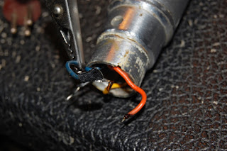

The original design is actually pretty cool. You have a case ground (black) a high impedance (blue) and a transformer coupled low impedance pair (orange/yellow), so you could cable select impedance. Reminds me of the old SM-57 transformer bypass mod, just so happens to be BUILT IN and optional on these.
That said, sourcing the 4 pin connectors for it now is something of a nuisance, and I want to reach for the low-Z mode anyway, so what you're about to see is an easily reversible disconnect of the high impedance (pre transformer) circuit.

Form factor is identical, I happened to have a couple three pin Cannon male inserts lying around, which turned this into a full "bolt on" mod.

The dirt and crud even lend a period correct feel to these, so as not to bum out the vintage zombies. I jest, partially.

So a bit of heat shrink on the blue hi-Z feed, connect chassis to 1, and I decided to jam orange as "hot" on pin 2 because it's a "warmer" color than yellow. Completely scientific like. Whatever. The mic works, I like the sound, it will get used.
Apologies, I don't seem to have taken a picture of the completed unit. It looks like the connector end of a standard microphone, my guess is that if that isn't explanation enough, this mod might not be for you.
Friday, April 11, 2014
Drilled out the rivets securing the back panel of the IRP Voicematic to allow a bit of useful modification.


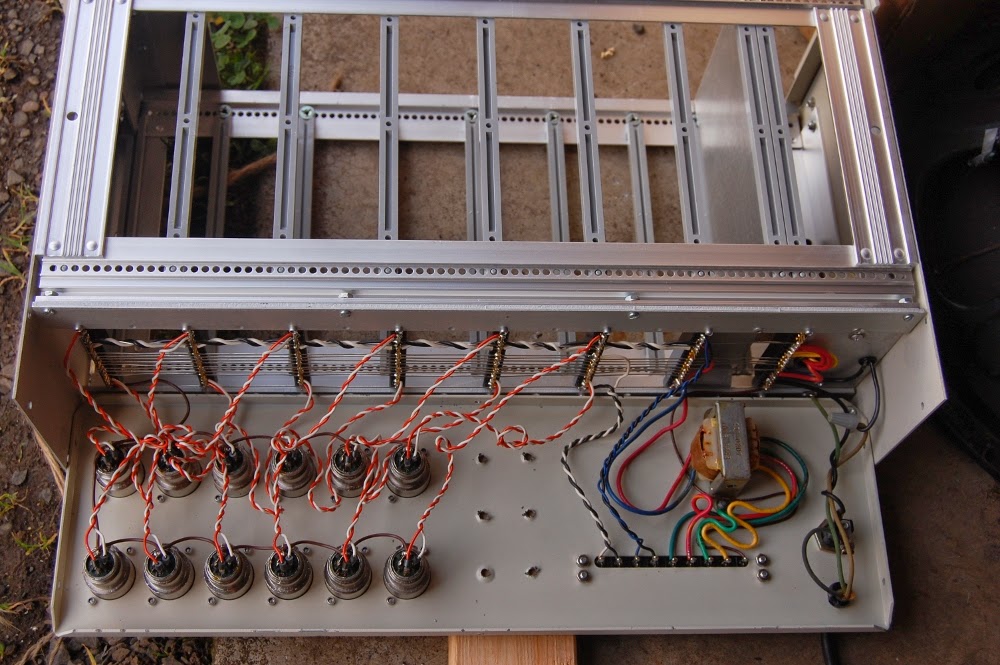
It's a little difficult to discern here, but there's an uninsulated wire in between the black and white twisted pair along the backplane buss. According to my scope, the bare wire is the audio feed line from the independent cards to the master summing section. Visible are my sloppily hand aligned holes.

The idea here is that since all the cards output direct to this buss wire, I can get away with installing interrupting jacks (Switchcraft 12A) so that the card feeds the tip directly, which is shunted to the combined buss when nothing is plugged into the jack. I've opted to only go so far as metal work on the 11/12 hole, as I don't have a card for that pair. So yeah, I'm leaving a HOLE in the case. Never know when it might come in handy.

Functional, though the recovery amplifier provides for considerable gain, so direct patching the two input card has a much lower level than what is available at transformer output. I guess that's what booster pedals are for.. HAHA.
Wednesday, April 09, 2014
Here are some more shots of the woodwork on the TIC 500 set (both of which are now recapped, and to varying degrees functional).
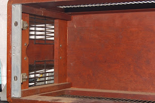


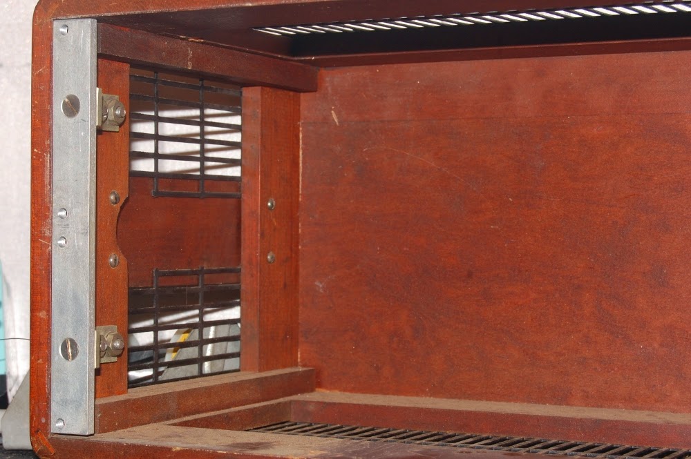
Assembly details, fairly apparent.

Precision.

Each unit is self powered, the large bodied grounded plug assembly just fits through this hole necessitating a keyway for other cord.

Another peek at woodwork, only one side is drilled like this..

..which makes for a nice view.

Though to be fair, the ample ventilation provides for largely unrestricted observation.

I found service data! TIC was evidently acquired by Acton Labs in the mid 1950s (or thereabouts), and in reading this thread it would seem TIC was H.H. Scott's company after departing GenRad? http://antiqueradios.com/forums/viewtopic.php?f=8&t=221316
Regardless, I'm happy to have a roadmap I can follow should I decide to tackle the motorboating issues. I'm somewhat on the fence about that, because of an interactive response to signal that nudges these into musical instrument territory.
Monday, February 10, 2014
Picked up a Technology Instruments Corp Dual Type 500 AR wideband voltage amplifier last year, because, well.. look at it.


Tired phrase, but: they don't make them like they used to.

Fairly no nonsense control set.

Yes, it glows in that logo.

Cracking the units open revealed a somewhat ugly bias battery assembly, comprised of two 625 mercury batteries bound together. This is only switched in at 1000 gain, and so I opted to remove it with the intent to replace in event of malfunction. My applications are confined to the audible spectrum of sound (as opposed to full 5Hz-2MHz claimed) so a little non-linearity may actually be welcome.
There's really only one way to find out.

Original circuit, gutshot topside.

Original circuit, gutshot from below. My intent is to replace the electrolytics and the selenium, and then give it a listen.

Modern parts make for a roomier experience.

A 100pf mica domino cap (visible on the original unit) has been installed on the wafer switch.

I've been going the budget route on electrolytic capacitors, building ugly little clusters costs less than a quarter of repop multisection can caps. These are not museum collection pieces, these are supposed to be used.

This was an easy fix that entailed shortening the power cable about a foot from the inside.

General purpose gutshot.

The earlier, original screw is quite evident compared to the newer screw, both of which exhibit a level of quality I don't see in a lot of current hardware.

So, after working one unit over I was slowly bringing it up on a variac and started to read voltage swings on output, one pulse every two seconds or so. Slow enough to confuse my multimeter on both AC & DC settings. The scope displayed a pulse that jumped toward the top of the scale, which indicated a frightful signal to be feeding gear downstream.
Plugging this 75 ohm terminator from my video junk into the input happens to snub the oscillation. It took me a little while to connect this particular set of dots.. after discovery of the motorboating, I shelved this for a while to clear my head. Then I observed that it didn't oscillate at 10, various resistors strapped on the output, loading the input with a signal source and listening to output, generally just fooling around with it brought about this observation.
So, the plan is to terminate the input with the largest resistor I can to prohibit runaway, which, I might add, only affects this unit (before and after recap). I dug into this one first because it was operationally impaired, so I could have a functioning unit to A/B while troubleshooting, should the need arise.
All in all, I would not describe this as a high fidelity preamp, it does however go deeply enough into the realm of character to justify having around. Plus, it's pleasing to the eye.
Subscribe to:
Posts (Atom)