Tuesday, March 29, 2011

Since I'm not going to be working on much for a little while I figure it's no disservice to cover something that actually works.


I picked up a pair of these telecommunications mixers several years back. Three microphone input channels under heavy noise gates and a feedback snubbing ducking stage, feeding an array of in/out connections that also drive the ducking circuitry. These do appear to operate on the "that what is loudest must pass" philosophy. No doubt this facilitated the ability of executives to interrupt one another hundreds or thousands of miles away.


Beyond the Aux input and PA output, the connection block at left is direct line input and output, the only level adjustment is set and forget gain scheduling accessed at the interior of the unit. The middle block is the telecommunications interface, presumably the built in loops only affect the in/out of the transmit/receive trunk. The bandwidth logic and array of other unconventional connections remain, for the moment, shrouded in mystery.


Mind you, I've got a bit of a handle as to the function of say "bandwidth logic", but even armed with the manual I'm taking it slow. For example, in contemplating the two connectors above I realize "TO IN" seems to mean "output" and "FROM OUT" sort of equates to an "input"; but then, in a nanosecond I re-read that as TO/IN and FROM/OUT. TO and FROM have no business being printed on the device itself, save the application trajectories for the installation manual.

I recall once, in the early 1990s of being invited over to a co-workers house to assist in troubleshooting his home stereo, which was non-functional. He had it wired IN to IN and OUT to OUT. Drawing from this memory, I realize I may be overthinking the connector block above, and yes, I do know full well that I should be able to determine direction in about 6 seconds of actual application.

Being pragmatic about the device would rob me of the satisfaction of bellyaching about its inherent obfuscation, and how else am I going to work big words into my discourse? Okay, I'll stop being a bore now.


ATE! They made the brakes for my Volkswagen. I know I am in good hands, even if that transformer is not interleaved.

What? I forgot to mention that being a telecommunications device, superior bandwidth is not a concern. This thing is purposed to plug into telephone lines and screechy little conference speakers. LoFi, eat your heart out. It does actually pass more bandwidth than 300-3400 hz, I have proof, but printed spec does fall short of 20-20K.


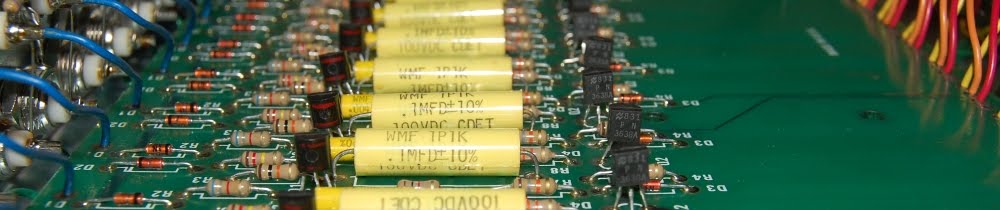
Here's a bunch of stuff that makes it work, that's where the magic smoke lives.

Sorry, seems I'm marginally loopy today, and it's time I scramble off to work..

Monday, March 28, 2011

No work surfaces make me cranky. I'm still on the Intersound Mini-Six. My work surface for this particular project up to this point has been, I shit you not, a Hallicrafters S-53 sitting on top of the Lafayette U-50 standing on its side.


Here's an overlay of the circuit components I pulled out of the malfunctioning negative side of the +/- 12 volt power supply.


Here's a pulled trace from extracting the master volume control, not really an impediment, just annoying.

In plotting my approach to repair this unit, I've opted for simple regulation in the power supply. A regulator, instead of a discrete circuit. I'm going to learn what I can from the original circuit, but as a matter of course I'm taking the easy way out for now.


Turns out I didn't have TO-92 regulators on hand either, so the legs of a TO-220 are trimmed to fit.


Next step should be obvious..

So, I slapped a voltage regulator in and fired it up.

Lo and behold, there is now a negative voltage! However, it is less than 12 volts; and establishing a negative rail has pulled the positive rail down by several volts as well.

It was at this point that the ludicrousness of sitting on a box on top of a milk crate while working on a "table" that essentially boils down to a balancing act really sunk in. All tinkering is in stand-by while I sort out space issues.

Take care of your work-bench.

Friday, March 18, 2011

Were TO-92 voltage regulators difficult to source in the late 1970s?


This 2N4403 is in the regulator hotseat with roughly -22 volts at collector, -16 at base and nothing at emitter. The 2N4401 on the positive rail shows much more reasonable voltages of 13.4, 12.6 and 11.9 respectively.


I'd like to know who drew arrows on this unit, and why. The arrow shown is pointing at the leg on which there should be voltage but is not.


More cryptic hints topside.


I'm tempted to gut the regulator sections and populate with 7812/7912.

Thursday, March 17, 2011

So, I made the offhand comment of planning to trim my set-up down to a single rack for a casual show tomorrow evening. Such statement was met with a bit of derision, to which I'll let my actions speak for me... instead of peppering my conversation with the satisfyingly juvenile "I'll show you!" and making an ass of myself.

Well, more of an ass than usual anyway.


My as yet unresolved mixer problem ceases to be a concern within the criteria I have set: nothing more than 16u of rack space leaving enough room for cables I'll need under the lid.

Enter the Intersound Mini Six 1u monophonic six input line mixer. My plan is to piggyback this unit with another line mixer in order to establish a wider swath of routing.


Not a whole lot going on here, the 1/4" output is in parallel with the XLR, allowing a feedback weave with the other mixer.


There's a bit of elbow room in here; no time to ponder the possibilities though, as this unit originated in the bad amp room and as such should be considered non-functional.

Visual reveals no burn marks, olfactory reveals no foul odors. The plunger power switch is sticky and favors a firm hand, which cultivates my optimism in regards to operability. See, the bad amp room was a dumping ground for stuff based on saleability, so, as has been confirmed already, originating there does not always equate to being broken.

I plug it in, push the switch, no pilot light.

Measure AC at switch and confirm operation, so the neon is shot, no worries. AC at secondary of power transformer, so far so good. DC at ICs evident at positive rail, but nonexistent at negative rail.


Perhaps it is running these 4558s on just +12 VDC?

Sidelong glance reveals open positions for additional ICs, currently it sits at two inputs per 4558. I'll file the observation of elbow room on circuit alongside the elbow room in the case and get back to the power supply, which is what I need to address prior to tomorrow evening.


I conclude that no, this unit is not supposed to be supplying a single +12 volt feed to the opamps, as the axial electrolytic cap at lower right is sitting on top of a negative voltage, which must be deadheading into an open circuit somewhere.

Time to connect the dots on the negative rail.

Tuesday, March 15, 2011

While my makeshift bench carries the burden of the Tektronix scope (effectively eliminating access for other things), I'll crack the case on another presumably operational unit for giggles.


Here's a Pelco VS512B twelve input electronic switch for multiple camera security monitoring systems. Operation is more or less identical to the simplest of analog sequencers, though instead of each stage passing a DC voltage corresponding to a potentiometer setting, each stage passes signal. Bandwidth is presumably up into the MHz, since it must carry video signal, low frequency has yet to be tested since the unit as stock is loaded with BNC connectors. Hole placement on this looks to be too congested for 1/4" jacks, so I may have to settle for RCA connectors on this thing.


Overall there seems a pretty light parts count here, considering. The twelve switching input sections at upper left, room for eight more. I believe far left is a gain recovery/buffer stage for the output. Power supply at right. Halfway into the frame is the rate pot, function switches below.


Input at left. Those diodes may play hell with signal integrity in the audio range, I'll leave them be for now. Red stripe actives are MCR102 Thyristors, presumably in a bistable daisy chain which translates to sequential switching. The locally (single channel) charged Thyristor could then tickle the PN3638A into conduction, sluicing the local input into the gain recovery stage for output.

Just speculation: The "ring" of Thyristors are the oscillator, cycle rate is dictated by the voltage supply charging up caps. Lock stepping this to an external sync pulse may be troublesome, but there is only one way to find out. Onto the pile with it.

Monday, March 14, 2011

Spent a few hours yesterday without electricity, always a nice reminder of paper books, ink and fire. Don't lose sight of that stuff my friends.

So hindered by the absence of a search function I wound up lackadaisically perusing my paper copy of the Mouser catalog, which led me to this image:


Naturally, I'm led to believe that their superior resistor product is illustrated on the left.

It's the image on the right that tickles my fancy, however.


I've been plucking the used/clogged activated charcoal water filters from the trash (if they make it that far) in order to secure carbon materials with which to roll my own hopelessly noisy carbon resistors. The material itself is doubtless contaminated with all manner of miscellaneous bullshit that wouldn't make it past the door of any self respecting factory with the pressing goal for rampant pasteurization. I also highly doubt the resulting resistors will be RoHS compliant.


After rolling the material out I let it dry a few days. It does indeed reflect a resistance. Actual assembly is yet to be determined; I'm thinking Pyrex tubing cut to length, conductive plug/leg cemented in one end, infill of material gently compressed, over which another conductive plug/leg will be cemented.

Values will be arrived at through trial and error.

I was planning on posting about this project once I had made a few and could outline the process, but that catalog image forced my hand.. their rendition of the poor substrate is strikingly similar to my material of choice.

Thursday, March 10, 2011

I'm preparing to briefly touch upon the ANALOG vs. DIGITAL debate (oh so tired a discourse), guess which side I'm going to take.

So, as determined last time I had a look at the Tek 556, it would behoove me to focus only on circuit elements that are upstream of the power switch, narrowing my attention to the mains filter. Easiest test was to read for continuity across the AC legs of the power jack, at the highest range I watched my DMM read lower and lower resistances. Digital meters send a pulse out one probe and weigh the voltage drop vs current delivered into the completed circuit to determine resistance between the leads. In this case the pulse was charging the capacitor meant to shunt high frequency line noise, so as the cap slowly charged the perceived voltage drop was less and less, delivering the false reading of a lower resistance. Clearly, sometimes easiest is not best, or even good.

Time to start sniffing around for a decent analog meter.


While it has been over a week, this hole retains traces of the odor of failure.


The inlet cavity of the Sprague filter also appears to have seen heat in the past. While this could be patina that evolved over the past 45 years, I don't trust this part, so it will go.


I highly doubt I can find another one of these with ease, and if I did I'm betting it would be of roughly the same age, meaning it would be "vintage" and there'd likely be some sort of premium on top of the decrepit part. No thanks.

Seems the easiest path before me is to build in a modern power conditioner in the space previously occupied by the large can of the Sprague. I toyed, for some fraction of a moment, with the idea of building the circuit inside the Sprague can, but the PITA factor coupled with not knowing what's inside the can (1966 was within the polychlorinated biphenyl era) sobered me up.


Not reusing the Sprague component will demand I change my hardware a little in order to mount the voltage badge, I'm thinking nuts.


Spot the high voltage wire!

Wednesday, March 09, 2011

An abscessed tooth really puts me off the map, being able to see straight seems to be a crucial element to my process. I'm back now, will probably take me a short while to get back into the swing of things.


I played a show last weekend, in my less than fully functional state, which led to a few modifications to my approach. First: I never got around to digging into my TOA RX-212, so my Fender 4216 was rotated into the set up. Second: I forgot the PSU for the tube Tektronix 161 and 162 modules seen center rack, meaning an entire branch circuit of my set-up was inoperable, and I could have essentially left a rack at home.

The first bottleneck was the clincher, as four oscillators, distortion, pair of ring modulators and the H-3000 is more than enough to pave a huge set. A huge sound seems to reveal headroom issues with the Fender desk however, as all presence and clarity was brutally stripped from the wash leaving an undefined murk coming out of the speakers.


I think this is shortly before I removed the tape machine from the equation, since the Fender console does not support simultaneous 1/4" and XLR output feeds I had run XLR output to the Otari for recording and daisy chain its outputs to the PA. Troubleshooting my sound quality, demanded removal of the tape deck, which was no great tragedy since my set was less than satisfying up to that point.

As it turned out, the Otari was not the problem, and only through ripping out my low end and leaning on HF (with the aid of a mechanical alarm bell) was I able to move around a little bit in the audio realm.

More fuel to repair the TOA, and inspiration to crack the case on the Fender and see what I can learn.

(Thanks to Heather Chessman for second pic)

Wednesday, March 02, 2011

The Tektronix R 556 got pulled out of the rack for inspection yesterday. The biggest mystery so far has been how a fuse blew when both legs of the AC mains should have been open at the switch.


Side panel open to show mains conditioner and primary fuses; no dead animals in here, removing one potential cause off my list. I'm also not convinced that the fuse selection was correct, the ten amp fuse being a 3AG 10A 32V.


Revisiting the fuses just now has brought my attention to a fact that has been eluding me. The 10 amp fuse is for 125 volt mains, and the 5 amp fuse is for 230 volt mains, explaining why F1402 (the open 5A fuse) is depicted as an isolated self contained circuit. At THIS point I am proceeding as if the fuse is in fact a red herring, the condition of the failed fuse is not what one would expect after an audible arc with an olfactory aftermath. Besides, the open fuse shouldn't even be in circuit!

The simplest explanation is that a tech harvested the 5A fuse, knowing the oscilloscope wasn't connected to 230 volts to use in something that required a 5A fuse. The dummy non functioning part was then inserted to load the twist-lock cap so it didn't wander off somewhere or rattle while the fan is in operation.


I can't bank on that theory naturally; it is, however, feasible enough to wipe my mind of preconceived notions that could otherwise mask the real problem. The above shot is the rectifier section, and for the moment it's not suspect either (thankfully).


An operational power switch shouldn't be a source of heat. I find this suspect, though each pole of the switch is either fully open or fully closed according to my multimeter (which isn't lab grade, so there may be a small fraction of an ohm there). I'll revisit the switch later on, what it's not doing is sticking closed, so my concern of stray voltage feeding the circuit while the unit should be powered off is, for the moment, satisfied.

Now I'll focus my attention on the components that are on the hot side of the switch, the FL1400 filter and the 0.1pf cap that is strapped across the mains.


On a lighter note, digging through Tektronix equipment is inspirational when it comes to lead dress. I'll strive to achieve a similar level of beautiful geometry when I start in on point to point modular builds.