Showing posts with label recap. Show all posts

Sunday, January 20, 2013

I was recapping my Roland SMX-880 a while back and got hung up on the fact that I hadn't observed the fact that the 10uf electrolytic at input jack was a bipolar. Quick test confirmed that this cap is situated in line with the signal, it is the first thing the signal hits.

I wasn't about to put some polarized cap there, so the unit was set aside to await a parts order. In the meantime I read a bit of opinion on the internet I found agreeable: "The best sounding capacitor is a piece of wire".

Brilliant. Upper right corner, I hadn't any plans to subject it to DC anyway.

Thursday, November 15, 2012

I've been fine tuning the Autogram AC-8, I had pulled the MXA-1 & LA-1 modules from the AC-6, as there was pronounced imbalance between the right & left sides of the audio feed. A little bit of swapping sorted this out. Mind you, this tuning had occurred while the studio monitoring system was piggybacked on the program output feed.

Such a configuration is less than ideal for a few reasons, being able to monitor the audition channel for one. Having access to a control room volume other than amplifier input trim or mix levels is pretty handy as well.

The problem was that while input/output feeds all terminate to barrier strips for easy interfacing with the rest of world, the monitor feed of the AC-8 was internally routed to onboard amplifier sections, so the original monitor connections are post amplifier speaker feeds. While I have few reservations on the standard of quality that Autogram put forth into this unit, I've already got a monitoring set up slated for use and have no interest whatsoever in using the MA-1 monitor amplifier between my ears and the work.

Fortunately the monitor modules are built on standard eight pin Amphenol as opposed to the nine pin variety that is used for input modules. I built a pair of cables to tap into the signal input of the amplifier connector and route that into my monitoring system.

Suddenly, able to A-B the theoretically identical program and audition channels against one another, it became very apparent that the AC-8 was overdue for a recap.

I had procured some new production axial capacitors a short time back to recap some modules. However, while I ordered them based on the physical package of the original parts (while upscaling voltage values as the existing components didn't allow for a healthy safety margin) I was greeted with the fact that the 100 uf were larger than advertised. This had delayed installation until my ears notified me that we'd passed from preventative maintenance into degraded quality damage control. In the above image, the MXA-1 module at right has the new caps versus original equipment at left.

In the above image, the LA-1 module at left has the new caps versus original equipment at right... and so on. If you scrutinize the upper left hand nut of the right hand unit you'll observe a mysterious residue that greeted me in one batch of modules.

In earlier attempts to balance out the stereo field I had plucked all the MXA-1 (mixer summing amplifier) and LA-1 (signal output line amplifier) from the AC-6, which has evidently had a much easier life than the AC-8 (based on comparison of interior module conditions). The LA-1 pictured above is from the AC-8, I know this because the AC-8 has an additional mono summing channel, resulting in five of each module type whereas the AC-6 does not. All five of the LA-1 modules are similar in condition (the MXA just have more signs of heat).

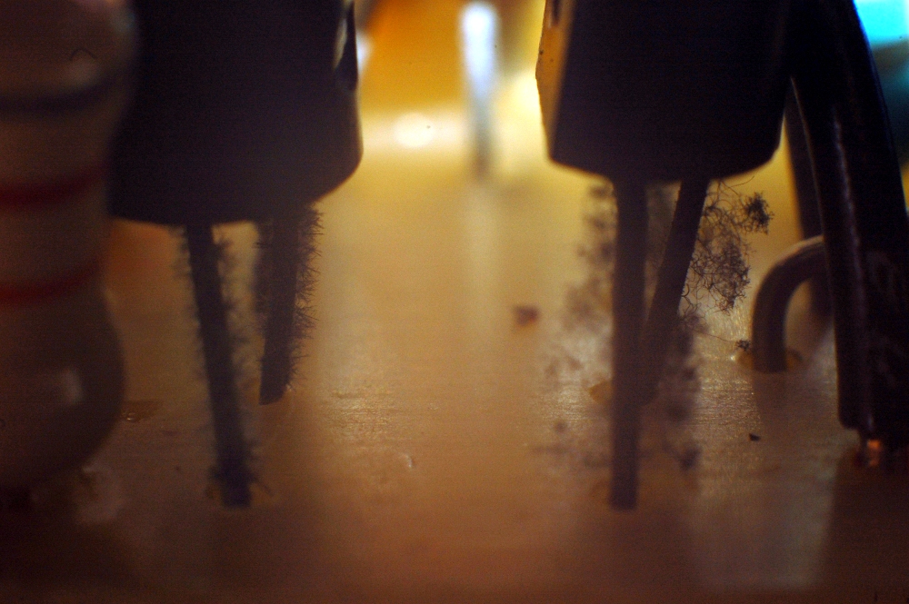
While the theory could be advanced that the big sound from this desk comes in part from the hairy legs of the savagely unfettered sasquatch looking transistors, I did my best to knock this stuff back a bit.

The audiophile skin effect theorists could have a field day with this.

Wednesday, April 04, 2012

"Something smells hot"

"Yup." eyeing the 70s solid state amp currently being punished by a Yamaha CS-01II - nope, it passed the sniff test just fine.

"Oh, shit." Don's Bassman 50, which was filling in for my Princeton in order to keep up with volume levels, was quietly blowing smoke.

Bassman 50 head chassis planted into a 1x12 combo amp case. I've seen uglier work, this thing could use a handle though.

Typical 1970s Fender gutshot, no surprises here.

The other end of the capacitor cover has a notch built into it to clear this screw, based on this I am under the impression someone has been inside this thing..

..they should have changed the caps while they were there. Early 73 & late 72 dated parts here; some smoky residue around those vent holes and olfactory evidence lends credence that these parts are done.

Either someone else has been inside this, or it was training day at the factory. I even briefly visualized a loose rodent chewing on the wires, but the markings are wrong & there is thankfully no further rodent call letters.

Looks like a simple fix just waiting out parts to arrive.

Wednesday, March 28, 2012

I'm slated to commence on a recording project this evening, so it's high time I get around to recapping the Langevin AM-301.

If anyone reading this has a spare couple of those red Rolo looking slider caps, I'm interested.

Another low parts count device, my favorite!

To the right is an upsized 33-50 (was a 25-25) CDE and 4.7-63 Spragues, but they are nigh on identical in appearance to the Nichicon caps in other values I procured. I miss the days of manufacturers celebrating their independence with unique and ugly colors (you know, when they made the stuff themselves..).

I decided to draw the line at recapping 4 (BEAD), retaining a pair of original (CF) and the pair of previously modified (HG, by an unknown tech at an unknown date) for comparative purposes. I've seen pictures of this mixer as a set, with EQ, limiting, etc, and am speculating that the traces that terminate at the end of the PCB can plug into additional modules (of which I sadly have none).

While the picture does not reflect this, I have recapped the master summing cards seen here. I have not yet messed with the 100-50 CDE Beavers, as to do that in a non-half-assed manner will entail actual disassembly (as opposed to actually reaching over and pulling open the flip up panel). I might be a lazy asshole and clip those caps out, loop the existing legs and install the new caps that way, but just typing that out made me cringe so that's probably unlikely. It will probably wait until I dig in to replace the channel 8 slider, unless malfunction forces me to tend to it immediately.

Power is single pole 48 volts DC. Makes it tempting to implement phantom power, though I could probably build up a small phantom power breakout box to piggyback that 6 pin Jones outlet with a lot less hassle and more ease of use. I do like the abbreviated "cue".

Tuesday, March 27, 2012

I'd love to say that during the past three weeks I have been neck deep in super secret R&D for fantastic contraptions forthcoming..

..but the fact of the matter is that I just can't get some parts to fit! Part listed as 8 by 11mm measures 11 by 22mm. I think I'll manage to squeeze it in there OK. I should manage some boring recap pics too in order to move along the content train.

Monday, September 05, 2011

What follows is my tactic for repetitive rework, such as is apt to be found in mixing consoles, multitracks and really bad production runs. As far as recaps go, this approach makes rather high part count projects only a little more difficult than a simple tube amp recap. In not necessarily the most accurate order:

1st, I plot out the position of all parts to be replaced and mark the PCB so I can desolder everything on my bench (say, two or three channels) in a single pass. My preferred method of desoldering is to heat the joint with the iron and use a 7874B type pump to remove the bulk of material. Once most of the solder has been removed on everything at hand I will go through everything while the iron is still hot and twist each part looking for movement of both legs. If a leg is still soldered in, it will be heated while twisting to free it up before moving on to the next one. Once all parts are loose, I'll snip the bent ends if they don't pop out freely, and drop them out. This has resulted in minimization of pulled traces.

2nd, each identical channel has the same parts count, this unit per channel count has been marked on the bags containing the parts.

3rd, I begin with the lowest quantity per channel parts (typically "1") and load those all first, no higher part count parts are removed from the bags until it is their turn. Only the unique or super low part count parts are removed from the bags (and ALL of said quantity are removed prior to stuffing a single part). Pictured here is the 330uf, 100uf, 33uf and 4.7uf loaded into the "active" circuit, while an already stuffed part reference circuit (very important to this particular process, though after a few passes the example gets less and less attention) sits atop a bowl full of pull jobs. In the foreground are five 10uf that are to be stuffed as soon as the camera is set down, leaving all remaining seven slots for the 47 uf caps.

Observe polarity. This particular board is designed such that all "east-west" positioned caps had the ground lead to the left, and all "north-south" caps had the ground lead facing me, from the position that I was working on them. This made perpetual polarity checks less of an issue, but it's certainly not a feature one should count on.

Once the lot is stuffed it will be checked for shorts (a couple of the pads are very close to one another), cleaned, then reassembled.

160 some odd caps, minus a few known to have fled from the bench.

Channels are all done, next up is the summing, metering and PSU sections. Then a proper clean up & burn in.

Saturday, September 03, 2011

Dug out the bench today, in hopes of getting a little work done.

The contents of this pan were strewn over the bench. You could say my junk box situation is a bit unruly at this point in time.

First tier of the actual progress pile is working through the Ramsa 8210 and freeing up even more space on the bench while also paving the way to record.

Each of the channel strips has been marked with its position in the frame, which I find odd, seeing as how the channel strips are presumably all identical, and actual channel number is a function of physical placement in the console. I doubt this mark is stock, and I take it to be a sign that someone has been inside this thing in the past.

Doing some fairly drastic work, from the look of things...

Cut traces and jumpers, I haven't really done a huge amount of research and/or reverse engineering on this yet. I'm toying with the idea of reverting two of the ten channels back to stock for comparative analyses, since eight direct outputs will mate with the recorder.

Then again, perhaps I'll just recap and reassemble for brevity sake. I will ponder what it would take to return a channel to stock before making a decision. I have decided to leave the (groan) RCA connectors alone at the rear. Since the Otari is technically unbalanced, I'm not losing anything with the form of the plug. My plan is to loom up RCA direct out/return and XLR pin 3 hot unbalanced snakes to a latching hard wired 1/4" patch bay, which will allow a no fuss interface to the rest of world and keep the weirdo connectors intact.

I only got one channel recapped, after preparing the bench. Though another channel has been torn down, and is ready for more caps (tomorrow).

Side by side comparison of the new and old. I'm loading it with Nichicon KW series, purportedly audio grade caps and inexpensive. Each channel carries 7x 47uf @ 6.3v (upgraded to 25v); 2x 10uf @ 25v (upgraded to 100v); 3x 10uf @ 63v (upgraded to 100v); 1x 330uf @ 6.3v; 1x 100uf @ 6.3v (upgraded to 25v); 1x 33uf @ 25v (upgraded to 35v) and 1x 4.7 @ 25v (upgraded to 50v).

Rest assured, I will be bolting these channels down out of the sequence printed on their frames, just because I can.

Saturday, July 09, 2011

It's high time for some shoddy photography. (Apologies, it was clearly not my day for running a camera, though I certainly don't feel like reshooting this as imagery is secondary to the process)


Enter the Ramsa 8210. For years this thing sat on a shelf in a back room at the music store I worked at over a decade ago. Even then it lured me a bit, but for one reason or other never made me reach for my wallet (probably because I already HAD a mixer and was/am perpetually broke).

During the big move it went home with a friend to start a new life.


But it would seem that all was not well in mixer land, the several year lapse in use (I reckon easily a decade) had done damage to the switchery..


Reducing the preferred characteristic of plug and play (most beneficial when dealing with creativity) into a hammer party of exercising the moving parts with varying degrees of success.


Meanwhile, the electronic side of things had also decayed in the rut of disuse..


Which would explain the fact that when I picked this console up as potential trade fodder it wore a VOC odor of ruptured electronics in the same way some people wear perfume. I actually had to roll my windows down on the drive home to tolerate it resting in the passenger seat.


1 out of 3 is not bad. In all likelihood, the capacitors had dried up beyond use during the many years of neglect; application of power just made them fragrant.


In doing some initial investigation regarding this family of mixer I found some pockets of praise, so there's encouragement to fix it beyond my own simmering curiosity. In working on it I am seriously considering ousting the RCA phono type connector for the more instrument friendly 1/4" phone plug.


All rear connectors are contained on a separate circuit board card, making a jack retrofit rather trivial (once the channel strips are removed for recap). Hopefully they can be fitted without interference.

Tuesday, July 05, 2011

Hahahahaha, so, "open the floodgates" apparently means "take a month off". I'm sure future installments will be spotty as well (see what I did there?).

Noticed a mildly acrid/sweet VOC sort of smell faintly emanating from the Roland SMX-880, which has been performing line mixing duties for living room sequencing. It wasn't until I picked up a Ramsa WR 8210 for trade, which positively reeked of this exact smell, that I decided to do something about it.

I've also noticed a recent development of fizzle on some high resonance/low frequency synthesizer decays and an over all squishiness in the low end. Hopefully this is a new development and not just me finally coming around to the facts after being exposed to mixing board odor.


Since I've deemed it unlikely that I'll find service data on this unit, I went about the classic count and scratch method to tally caps (note indelible ink marks on capacitors).


The inputs are simple discrete sections, which I've more or less failed to photograph very well here. Sound quality (even now) is warm and full when compared to the modern lofty frequency response/high slew rate low headroom cookie cutter fare that fills out the ranks of low priced mixers these days. That said, it's not lush and there's a distance grit that overlays everything. I like the sound quality of this unit, though I do hope to tighten up the low frequency and lose some distortion artifacts. I guess time will tell how much of the warm girth is actually out of tolerance parts.


Over all attention to detail, as evidenced by this printed circuit star ground plane, is promising, and I look forward to replacing all the caps, washing the PCB and giving this thing another span of useful life.

Wednesday, December 29, 2010

Recapped the B+ power supply of my 1973/4 Fender Princeton last night. This is the amp that had sat in a shed for a while and sounded anemic as hell in a raspy farting through a cork wall sort of way. The main problem was not a failing speaker as the seller thought, but a lifted ground reference in the phase inverter section that proved a simple fix. The amp was far from done, needing the logical next step: removal and replacement of 37 year old electrolytics.


Since the overall amp is so compact, I faceplanted the cabinet and used the upper rear baffle railing as my chassis stand.


Here's the original equipment, a Mallory axial 20MF hailing from the 43rd week of 1973 and a Mallory 40-20-20 multi-section can cap built in the 29th week of 1973 (you'll just have to trust me on that one).


Can caps that tie to the chassis require a nice solid structural solder joint that completes ground and secures the cap to the amp. For this, liberal application of heat is a thousand times better than trying to remove and replace a chassis pool with an underpowered or small iron. Here's the 100 watt Weller I use for chassis work in comparison to the variable temp iron I use for all other component grade work.


Of course, with a behemoth hot iron, all of its benefits in this single application are detrimental in every other way. Shifting of existing components that would otherwise be untouched is crucial; I've smelled enough melting plastic already, thanks.


This tab got the desoldering treatment, I'm about to bend the tab up and free this joint. The joint on the opposite end proved easier to just heat and rotate the can, shifting that tab out of the pool. Then it's just a matter of bending the remaining tabs up and dropping the old can out.


Ancient (remember, electronic eras pass faster than those of humans) solder flux reminds me of cerumen, and it too is generally undesirable when built up and can take multiple passes to get clean. Above shot is after a single scrub/soak pass of isopropyl, and yes the good people at Fender put that flux there in the first place. I have a few cotton swab heads full of the stuff if any collectors are interested.


Now it's ready for a new cap. I'm not concerned over the existing solder there and think of it as tinning for the new joint.


The replacement multisection is built by CE Manufacturing in the US, purportedly off the original Mallory tooling. In comparing parts side by side I find that very easy to believe, fitment was EXACT.


Somewhat hard to see, but the pull job here has a bulge in the center vent.

I bought the caps in reference to the schematic as opposed to referencing the actual amp, which is why the replacement multisection is a 20-20-20 as opposed to the 40-20-20 that was original. Frankly, I'm not overly concerned at the 20% drop in total capacitance of the power supply. It seems as if manufacturing tolerances of electrolytics tend to over build as opposed to under build, and I've heard people bellyaching about adverse effects that over capacitance has on tone. Seriously though, retrofitting a lower capacitance to follow the mid 1960s circuit isn't a life or death matter.


Here it is, ready to burn in slowly on a variac. I'm not in love with the recreation of the original joint at the head of the axial cap, but it seems solid enough and the other did last for 37 years just fine.. I only addressed the B+ caps for now as this is my amp and I expect to be in and out of it for a while; tinkering with the guts and getting it just right to my ear, so COMPLETE overhaul is less of a pressing issue. Once I've insured a solid electrical base, next step is to rotate through a pile of 10 inch speakers to find the best match for my practice and recording needs.