Showing posts with label tubes. Show all posts

Monday, February 10, 2014

Picked up a Technology Instruments Corp Dual Type 500 AR wideband voltage amplifier last year, because, well.. look at it.

Tired phrase, but: they don't make them like they used to.

Fairly no nonsense control set.

Yes, it glows in that logo.

Cracking the units open revealed a somewhat ugly bias battery assembly, comprised of two 625 mercury batteries bound together. This is only switched in at 1000 gain, and so I opted to remove it with the intent to replace in event of malfunction. My applications are confined to the audible spectrum of sound (as opposed to full 5Hz-2MHz claimed) so a little non-linearity may actually be welcome.

There's really only one way to find out.

Original circuit, gutshot topside.

Original circuit, gutshot from below. My intent is to replace the electrolytics and the selenium, and then give it a listen.

Modern parts make for a roomier experience.

A 100pf mica domino cap (visible on the original unit) has been installed on the wafer switch.

I've been going the budget route on electrolytic capacitors, building ugly little clusters costs less than a quarter of repop multisection can caps. These are not museum collection pieces, these are supposed to be used.

This was an easy fix that entailed shortening the power cable about a foot from the inside.

General purpose gutshot.

The earlier, original screw is quite evident compared to the newer screw, both of which exhibit a level of quality I don't see in a lot of current hardware.

So, after working one unit over I was slowly bringing it up on a variac and started to read voltage swings on output, one pulse every two seconds or so. Slow enough to confuse my multimeter on both AC & DC settings. The scope displayed a pulse that jumped toward the top of the scale, which indicated a frightful signal to be feeding gear downstream.

Plugging this 75 ohm terminator from my video junk into the input happens to snub the oscillation. It took me a little while to connect this particular set of dots.. after discovery of the motorboating, I shelved this for a while to clear my head. Then I observed that it didn't oscillate at 10, various resistors strapped on the output, loading the input with a signal source and listening to output, generally just fooling around with it brought about this observation.

So, the plan is to terminate the input with the largest resistor I can to prohibit runaway, which, I might add, only affects this unit (before and after recap). I dug into this one first because it was operationally impaired, so I could have a functioning unit to A/B while troubleshooting, should the need arise.

All in all, I would not describe this as a high fidelity preamp, it does however go deeply enough into the realm of character to justify having around. Plus, it's pleasing to the eye.

Saturday, December 07, 2013

200th post! Let me take a moment to explain my extended leave. The notion that I was starting a bunch of threads then leaving them out to wither and fade away was weighing down on me a bit. See, as I would climb the archives for a kernel of data (these posts are probably more for my own benefit than anyone else's, though I do appreciate the support and positive feedback when it comes up) it became more and more apparent that the greater majority of my posts were either showcasing an object (not my intent) or lacked closure.

In short, it really seems a scatterbrained collection of halfway theres, and I made the command decision to NOT "pollute" these logs with more half finished business until something started was ushered to completion. That something is the outboard reverb build I have been dancing around for more years than I care to contemplate. So this blogging process was shelved while I did other things, make no mistake, I haven't wandered away from flowing solder - I just couldn't bring myself to post about anything other than the reverb, until it's done.

Yes, it really has taken me months to move on beyond chassis layout and punching holes (arguably more involved) to actual circuit wiring (you know, the FUN stuff). Ask me about painting my car next.

No, don't.

At any rate, progress has been made so here I am. For those that don't already know, the Fender 6G15 reverberation amplifier is loosely based on the Fender Champ - driving a spring reverb tank in lieu of a speaker, with an additional gain recovery/dry mix stage on the output. For reasons I have quite simply forgotten at this point, I decided I wanted to oust the 6K6/6V6 Champ inspired power section with a 6BQ5/EL84 single ended section. So, since I have one underfoot that I can observe directly, I turned to the Kalamazoo Model 1.

However, while the Champ and Model 1 are of similar class, they are of different pedigree. There were strengths I wanted to combine, and so we launched into hybrid territory.

Make no mistake though, when it came down to actual assembly I did not consult the gods of audio. I grabbed whatever I had on hand, you know, like the Old Masters did. Pictured above is the initial 12AX7 tube, first stage at high numbers (socket pinout) feeding a preamp gain (dwell) ala 6G15. This returns to the low numbers triode which is wired up more like the Model 1 sans tone control feeding the power section.

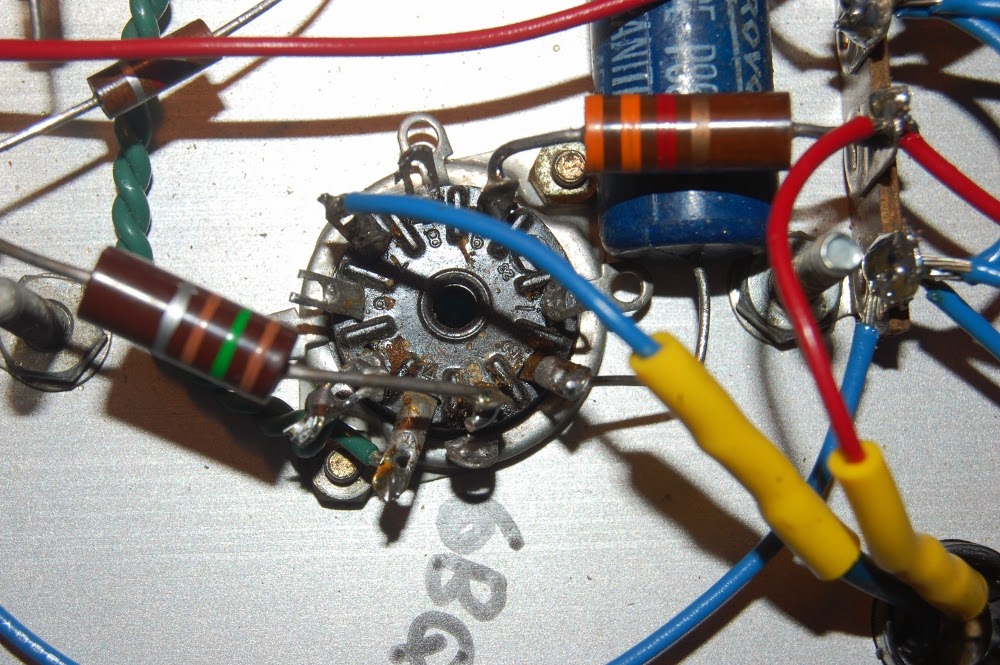
Here it is evident that I am using previously built components, and did not exert a lot of care in cleaning the vestiges of whatever this used to be. It's a 6BQ5 single ended power section now, please ignore any other disarray. AT LEAST I DIDN'T LEAVE REMNANTS OF WIRING!

I'd like to note that while the power amplifier stage is pretty much lifted directly from the Kalamazoo, the B+ power supply feeding it is a choked configuration more in line with the 6G15. The single ended amplifier stage feeds an output transformer coupled to a spring reverb tank.

The return from the reverb tank is seen here, direct coupled to the low numbers side of the 12AX7 gain recovery tube. This feeds a tone control connected to the high side of a mix control to output. High number side is a cathode follower dry feed taken from input jack, which drives the low side of the mix control.

Depicted above is the aforementioned tone and mix controls. Allow me to name off the imbroglio of capacitors, as there is no single photographic vantage point that could make sense of this mess.

The burnt sienna .03@600 CDE to the left is the DC blocking input cap for dry stage. Grid is elevated ~ 100 volts or so, and this fine capacitor is what keeps that off my pickups (or transistors, opamps, transformers, whatever.. outboard spring reverb will see more duty than just guitar).
The cyan/turquoise .1@400 is the DC blocker at dry cathode follower to mix pot (at right).
The .01@400 Sprague Black Cat is my reverb recovery section coupling cap to tone control. I think this should actually be a .1, that's a mistake (see if you can spot two more amidst these pics!) but I guess I'll leave it be unless reverb return sounds too thin.
The black .01 disc cap is the tone cap from control to ground, doing what it can to shunt ALL my signal away since I botched the coupling size.
The domino mica cap is a 500pf coupler from tone wiper to mix. I figured I would double the 6G15 design of 250pf here, because, well, you know, I like a little bass. Hahaha, apparently this was a wasted effort. I'll revisit this later. We're not done yet.

Before anyone pipes up about it, yes, I am aware of capacitive coupling, lead dress and ground loops. Thankfully I'm okay at (read as: used to) working in tight configurations, what with the rework I have in store.

The unit is going to be a controls on face, at bottom type of configuration (ala Marshall heads); so this is the natural finished stance of the chassis. Rear support is not going to be via standoff, it will be supported all sides by wooden runners.

So, with everything more or less squared away I set about the initial slow warm up on a variac. Something, however, was amiss. My voltages were way off, B+ being abnormally low. Concern with a short circuit proved unwarranted. Everything tested out okay, it was just that my B+ leg was reading roughly 10% of expected.

I had tested this transformer prior, and it was concluded to be a ~500 volt center tapped secondary. You know, because I measured it. Having the luxury of an uninstalled identical transformer I conducted the measurement test again on a part out of circuit.

Imagine my surprise when it turned out the high voltage secondary of my chosen power transformer was in fact delivering only ~50 volts across the windings! DECIMAL POINTS MATTER.

Above is an example of finished fitment, tight gap between the tube and chassis. Too tight? I'd probably bevel that on a production unit, but this is not, so..

Anyway, I'm wary about trying to fit enough discrete voltage multiplier stages to make use of the 50 volt center tapped PT work, so I'm thinking about piggybacking another transformer in there, either something with a proper B+ right out of the gate, or a step up I can drive with the 50 volts (I think a 120:24 volt transformer may work nicely here). Sadly, I couldn't find a correct voltage range with identical mounting in my piles, so the fix may wind up being less than visually perfect.

Of course, it'll all be encased in a cabinet anyway. Stay humble!

Sunday, April 22, 2012

Yesterday saw a little progress on the modification of the Traynor YBA3 Custom Special

The amp had been red-plating. As it turns out, this 150K dropping resistor (the bias supply is fed from the full high voltage B+ secondary, knocked down and separately rectified) had drifted up to 234K, and the 15K between cathodes of the bias smoothing capacitors had been replaced with a 45K flame proof, effectively tamping the available bias voltage down to useless levels. Hence, a bit too much current flow through the tubes.

Since this amp is purposed to be a player, and is already far from pristine, I'm comfortable with performing non-reversible modifications on it. To facilitate an adjustable per tube bias tap I undid the original bias feed at output tube grids (the connection above the nut) and removed the two 220K resistors. Full bias is now delivered from the adjustment pot to pin 1 of output tube and a 270K half watt carbon film resistor connects pin 1 (G3) to pin 5 (G1).

I also plucked the 1K5 grid resistors flanking the yellow 0.1 @ 600 coupling caps. As you may remember, I had questioned the lop sided approach to the inner and outer pairs of output tubes. I figure this is as good a place as any to test the effects of resistor distortion, so I planted 1/4 watt 1K6 carbon comps on every output tube signal grid. I realize there's negligible DC drop at this point, but I had the resistors on hand, so...

In order to minimize the flying parts construction, this modification entailed physically switching the alignment of signal path at the post phase inverter coupling caps seen here. Since I had already gutted everything on the "upper" row, switch over was easy. This move the DC bearing phase inverted signal back over the circuit, but the AC feed to the output section is a straight shot as opposed to incredibly long flying leads. So, I'm cautiously optimistic that I haven't destabilized the amplifier do to messing with lead dress (and I'll know where to start looking if instability is a problem).

I did have to create another chassis ground connection, the preparation of which involved removing patina with hardened steel (a chunk of razor blade). Metallic dust was removed by magnet. I took some close up pictures, but the razor thin depth of field didn't do me any favors. So those pics are not included.

One 100 watt soldering iron later.

Here's a sidelong shot of the modified output section before I reconnected the feedback tap at output. 2 watt 560 ohm screen resistors were also added, this is on top of 1K drop on the screen supply, which may be adjusted depending on performance seeing as how the 1K is made up of two 500 ohm in series.

The white cloth wire connects tube cathode to test point, which is connected to ground via a 1 ohm resistor.

I've done uglier work. I'm not elated about the aesthetic appearance of the screen buss (upper yellow wire) and the eyelet connections ofr the bias supply are a bit congested with the trunks of red & white wires, but over all there remains room to work and everything is electrically sound.

Another angle on the same stuff.

Over all guts. The ten footer view isn't half bad. I'd like to belt the three Sprague Atoms on the left down, but construction grade double stick tape will have to work for now (they've not given me any problems).

In order to give AC mains and the body of one of the 10K pots a comfortable berth, I had to rotate the fuse holder. Since the chassis is punched with a D hole, this entailed a pass with the file. The scuffs on the rear panel being a typical rookie mistake (I'm embracing the scratch & dent look on this amp) moving along...

Here's the finished set up. I slapped in a matching set of 10K pots since the picture of the mock up (THANKS DAN!). However, I haven't yet had the opportunity to test this, since my benchtop variac suddenly has a failed outlet and the other variac at hand has an intermittent short that was swinging the ammeter once it hit 50 volts.

So yeah, I expect some more variac discussion on the horizon.

Friday, April 13, 2012

Tuesday, December 20, 2011

Mystery amplifier!

Beyond this being another hot chassis amp with series string AC mains filament, I'm at a loss in terms of identification. That is not to say that it does not have any identifiable or rare qualities, rather, there's no visible mark manufacture, and plugging search terms based on what I do know and conclusions I've drawn based on the object itself, I keep getting flooded with results that do not match.

You can call me captain Run-On-Sentence, thanks.

From left to right, three 6AV6, a 50C5, and a 35W4. Supporting passive components litter the topside of a printed circuit board. I'm forwarding the guess that the caps are not original. The presence of a fuse is a nice touch.

Early printed circuit board.

Three inputs..

..chained together. Some sort of load resistor here may have improved multiple instrument performance. May have... I do not approve of the mechanical ground reference either, but if I'm going to spend time critiquing every last aspect of what was originally a cheap amp we'll be here all day.

A trio of 6AV6. I've seen these in a variety of amplifiers, as the triode section carries similar characteristics to the 12AX7. However these are single triode / dual diode valves, and anyone familiar with building fuzz circuits should already appreciate diodes. I've yet to see a 6AV6 deployed in a stock vintage amplifier that makes use of the diode (for distortion purposes, AGC and detection do not count). I have run signal through these diode stages, and while it takes a healthy level of voltage to make it work, I found it wholly worthwhile.

Of course, I like noise. It is safe to say that this isn't a holy grail of classic popular guitar tone, but it's also safe to say that there are those among you that are not purists. We'll touch upon this tube later on.

Those grey dog bone resistors make me think Japan is the likely candidate of country of origin, but again, it's a mystery.

Another shot of a 35W4 silkscreen. I really have no good reason for the these last two shots, other than it being easier to discern what the tubes were by looking at the pictures than by looking at the tubes themselves.

50 volt filaments, I'll find a spot for you yet.

Friday, December 16, 2011

It was bound to happen eventually. The sculpted bent metal styling that was more or less standard through the 1950s gave way to the angular bent metal that got a foothold in the 1960s. Those are of course generalizations in terms of time frame. There was slop on each side of that date line.

This clearly dates to the 1960s. The fact that someone painted the front panel exaggerates the ugly institutional aesthetics. Here's the intact lettering of a gutted one:

Still isn't winning any design of the year awards, though to be honest I enjoy the ugly angular stuff from the institutional schools of thought about as much as I enjoy the sculpted and primitive platforms from previous decades. Since this stuff is all by and large older than I am, I'll tip my hat to a little respect.

12AX7 weighing in at lower right, one half supports phase inversion for the push-pull output, the other half supports the "MIKE" input. The 6AU6 in the logical position of phase inverter is the line level input/second gain stage for microphone. Can't overlook the pair of 6V6 on output.

It would appear there have been sticky fingers where rectifier tubes are concerned. The red cover at upper right covers an octal plug for input configuration, pictured is the optional Newcomb input transformer. The installed Newcomb part number SF-30 could be confused (perhaps "substituted" is more applicable) with a bit of bent solid copper wiring, ala Romex.

Nothing incredibly odd here. The mains wiring does not appear to strictly adhere to the schematic (following), and the Foster output iron is hanging tough gut-side.

Another octal output connector (the Stromberg Carlson is, of course, wired differently).

I will always be delighted when I open an amp and have access to the schematic. Manufacturers take note!

In boosting the contrast on this image, I noticed a bunch of darker squiggly lines. Which, as it turned out, were present on all recent shots. See, a week ago I noticed a dark spot that was also spanning all images in the same location - indicative of a speck of dust on the face of the sensor. I tried to blow it out, which delivered a spot of spittle. At this point I had to go into fog & clean, and the soft cloth I selected managed to deposit small fibers everywhere. So, the camera is going to get a proper clean once I find my bulb brush, in the meantime I'll live with the artifacts.

Back to the amp, it would appear as if this has been modified as the plate on one half of the 12AX7 is hanging in open space.

CTS potentiometer dated 28th week of 1966.

Foster power transformer dated 31st week of 1966. The electrolytic can cap is dated 3rd week of 1967, that should probably be updated.