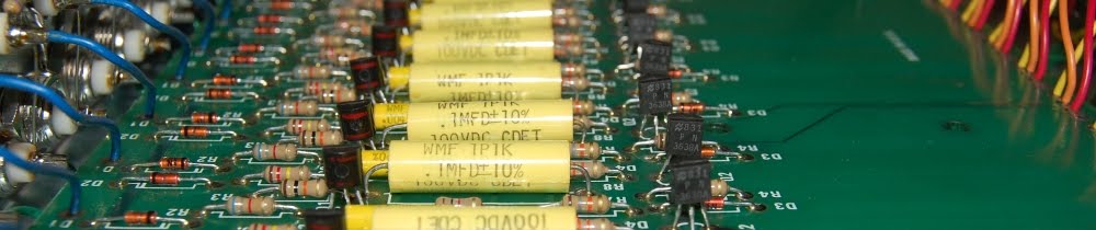
Showing posts with label switch. Show all posts

Saturday, November 08, 2014

Whew! So I have to remind myself how HTML works every time I post. Clearly I'm not being active enough, but rest assured, the wheels have been turning in the background. I've got a couple "filler" angles I can exploit, and while I detest the notion of coughing up fluff, if I have to stop and think about how to break a new paragraph something has to give.

Anyway, been tearing down some organs lately and have wound up (literally) wading through piles of interesting parts.

Low tech switch design. Left depicts an open condition, right depicts an operational failure. Easy fix, of course; sort of like brushing the bugs out of an early computer.

Lots of gritty potential.

More 1970s analog drum machine guts!

Daughterboard sounds as follows: #5 = BASS, #3 = SNARE, #4 = CLAVE, #6 = CONGA. Presumably the BRUSH, CYMBAL & SANDBLOCK (?) are handled on the inductor laden side of the main board. I'm a bit apprehensive about snare being built around the same circuit topology as bass & conga (the daughterboards are identical PCBs stuffed with different values), but whatever the sounds I have to thank the good people at Gulbransen for clearly labelling voltage supply points, etc.

I guess I should mention that the lowest daughterboard in that picture is a signal amplifier, not a one shot oscillator. I'm too fond of individual outputs to leave that section alone, but I'm certain it will see use in some capacity.

Once I scrape the dust off this it'll be a snap to try out.

Sunday, December 23, 2012

Okay, I've known about the Otari XLR pin 3 hot configuration for quite some time now, but in practice I'd never run into a catastrophic failure because of it (that is to say, I was able to record and playback audio on the 2 track machine with little issue). Therefore, that bit of information sunk into the dusty corners of my mind where it was wholly ignored. Of course, all that free riding came to a screeching halt once the Autogram AC-8 was planted in the audio control trunk. See, in my wiring up the output I included unbalanced 1/4" phone plugs which were at one point normalled to the monitor amplifier.

So, when I connected the pin 3 hot, pin 2 ground configuration of the Otari to the pin 2 hot pin 3 neutral (actually earth referenced thanks to my inclusion of unbalanced 1/4") configuration of the mixer output, a whole lot of nothing happened. Nothing to the tune of even killing the monitor feed to the amplifier.

I had entered into really easy diagnostics, unplug cable = sound, plug it in = zilch. So, with a nod to the widely published pin 2/3 issue, I built a pair of XLR cables with pins 2 & 3 swapped. Solved. Of course, at this point I recall a few months previous while I am working on the basket case MX5050-8 and can't get any channel response out of it, which, at that point was a step backward but given the hard life the machine has had I place it closer to the parts bin. Why yes, I had been feeding it audio from the Autogram while failing to get signal, it was just prior to the monitor amp feed modification.

So, the 2/3 swap XLR cables worked here too. I was able to commit signal to tape and playback (on conventional XLR), and it sounded good. So, my options now are to make another 6 pin swap XLR cables, or just modify the machine to reflect pin 2 hot. Ready to cut traces and jumper stuff at board level, I was met with this magnificent sight. Build six special purpose cables, or simply rewire 16 connectors?

Easy decision.

I did this, from poor placement in a room (that gets gear hauled in and out of)...

..and this. Very preliminary internet searches do not favor the notion that this is an easy & standard current production off the shelf part. Since the switch still works I think I may drill a small pilot hole in the lever portion and turn down a bit of small bar stock to have an end pin, then epoxy the new arm in place. Worse case I'll still have to find a replacement switch.

Since this machine got hammered the interior finds include stuff like this, from the side panels.

Wednesday, April 25, 2012

YBA 3 Custom Special Update

...or, it's not always what you suppose it is.

Armed with another variac I resumed an easy ramp up of voltage to insure everything was copasetic and wouldn't you know it, about 50 volts in I hear the "pung" of inrush current draw. Explicative deleted. So, it's NOT the test gear (except, of course, for the one with the faulty outlet). Troubleshooting ensues.

Amp was tubed with dummy load and the stand-by switch was set to play.

1st step: Remove tubes & repeat procedure... "pung"

Explicative deleted. After checking over my work and running continuity tests across the circuit to ground (both of which passed) my thoughts drift to the power transformer.

2nd step: Fire it up in stand-by to see if it's a shorted primary. Acts fine. What changed?

Hmmmm. Continuity check on switch reveals that while the pilot light side switches as intended, the center tap to ground portion (switch is pictured in the stand-by position, nearer half under scrutiny) exhibited high resistance when it should have been a dead short. Several actuations confirm the switch is garbage and needs to be replaced.

So, I theorize that the "pung" at the variac was instigated by arcing across the switch feeding inrush to the capacitor bank of the B+, and it probably wouldn't have been noticed if I cut the amp loose on full mains voltage instead of pussyfooting around. This also provides a satisfactory reason why all my voltages were wonky at the sub 50 volt position of the variac.

I did ponder the option of simply cleaning the switch contacts, since I have access to them.. but somehow every time I think along those lines I am hounded by the image of villagers with pitchforks and torches. Best to swap the part out entirely.

Tuesday, March 15, 2011

While my makeshift bench carries the burden of the Tektronix scope (effectively eliminating access for other things), I'll crack the case on another presumably operational unit for giggles.


Here's a Pelco VS512B twelve input electronic switch for multiple camera security monitoring systems. Operation is more or less identical to the simplest of analog sequencers, though instead of each stage passing a DC voltage corresponding to a potentiometer setting, each stage passes signal. Bandwidth is presumably up into the MHz, since it must carry video signal, low frequency has yet to be tested since the unit as stock is loaded with BNC connectors. Hole placement on this looks to be too congested for 1/4" jacks, so I may have to settle for RCA connectors on this thing.


Overall there seems a pretty light parts count here, considering. The twelve switching input sections at upper left, room for eight more. I believe far left is a gain recovery/buffer stage for the output. Power supply at right. Halfway into the frame is the rate pot, function switches below.


Input at left. Those diodes may play hell with signal integrity in the audio range, I'll leave them be for now. Red stripe actives are MCR102 Thyristors, presumably in a bistable daisy chain which translates to sequential switching. The locally (single channel) charged Thyristor could then tickle the PN3638A into conduction, sluicing the local input into the gain recovery stage for output.

Just speculation: The "ring" of Thyristors are the oscillator, cycle rate is dictated by the voltage supply charging up caps. Lock stepping this to an external sync pulse may be troublesome, but there is only one way to find out. Onto the pile with it.