Monday, November 28, 2011

High time I crawl through this Vortexion Type 6+2/S.M. vacuum tube mixer.

Early stereo, with six inputs for left channel & two for the right channel. I've toyed with the idea of routing the top & bottom four channels to each output, but this is another one fated for the live & let live pile for now. I'll consider butchery (sung to the tune of realigned signal wires) once it's up and running.

1/4" phone inputs & outputs, not much confusion here.

This input jack gave birth to some sort of insect. It's number 1!

Gutshot, underside. Clean and simple layout.

Innards, topside. Clean and simple continues to spill over.

EF86 pentodes performing signal amplification duties.

Leaking electrolytic, courtesy of mid century Hunts Capacitors. Not surprising after half a century.

Closest thing to a date code I could find, 13th week of 1957 it would appear.

At the time of this pic, I had been considering ousting the OE Bulgin power jack, which will require an input connector for the pictured Nanaboshi NCS series connector that was harvested from the Rigaku salvage. This would require enlarging the hole, but since this is a 240 volt mains device, a special power cable is in order anyway. However, while I haven't busted out the datasheet & caliper to confirm, it would appear tat the as stock mains inlet is a Bulgin PX0429, which will accept either the PX0430/SE (right angle) or PX0646. So, in short, buying a new end for a cable I'll have to make anyway is highly preferable to executing metalwork on vintage gear.

Sunday, November 27, 2011

About 20 years ago I dumpster dived an old Panasonic WV series Newvicon video camera and its broken VTR (which still supplied power) and fell in love with video feedback produced with the negative image function engaged. Sadly, this camera wound up stolen in 1993 while enjoying my first taste of communal living. Every once in a while, for over a decade, I would reminisce about that set-up and bemoan the fact that I didn't have a very solid footing in regards to rebuilding it, as I couldn't recall what it was. Of course, as my internet literacy grew I became a bit more proficient in searching, and eventually the string of widely spread out casual searches bore fruit.

Armed with the name of manufacturer & the type of element I was after I began my patient hunt, and eventually landed a good deal on a WV-3250 with power supply.

Of course, with one source comes the desire of additional input flexibility, so the search for a video mixer came next which led to this early example from Panasonic the WJ-545P.

Inputs & outputs are primarily UHF connectors.

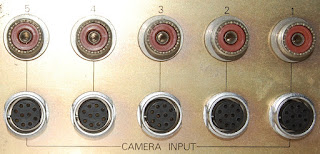
Support for 5 cameras (the mixer only handles two channels at once) includes the EIAJ 10 pin connector that the Panasonic camera has, though the voltage feed that the camera requires is absent, so external PSU is still required. This would be an easy enough fix, though very low priority since I have the external supplies already.

At lower left of the above image is the wired side of the EIAJ connector, further reinforcing my satisfaction with using the external supplies. Also evident is a single wire ground buss that ties to chassis at one point.

I think very few machines were bothered by the construction of this unit.

You don't really see this sort of build outside the DIY circles any more, which is sort of a shame.

...unless you were the one assembling these, one right after the other. All grey wire is shielded & tied to ground wires.

TO-100 package IC in a protective sleeve. The IC count on this thing is fairly minimal.

Saturday, November 26, 2011

A rare clear and warm day in November enticed me outside to snap a few shots of this Honeywell T6GA-600 galvanometer amplifier.

I'm speculating that this unit would originally be deployed between a sensor and a readout or graphing system, and I expect it to handle and pass DC. In passing a little time with the search engine, I found a patent application submitted by Honeywell five years after the build date of this T6GA in which they are attempting to solve the galvanometer frequency limitations (inability to operate in the 25,000 cps range). So, I haven't lofty hopes in regard to frequency response, even though 25 khz is off the charts for most people. I've been seeing a lot of references in the 100 hz range for standard, original purpose application, which DID include mechanical movement, so I'm hopeful that at least something will pass through this thing.

I found another document, published in 1966 under DOD (US Department of Defense, not the effects maker) contract dealing with "the Biological Effect of Blast from Bombs" which is just as gruesome as one would expect, in which the Honeywell T6GA is performing a supporting role between piezoelectric gauge signals and an oscillograph recorder. While they mentioned a low frequency response, I would venture that a percussive blast requires a certain level of prompt reaction, so I really don't know what to expect. I know, I know, just hook something up to it and pass signal already! Patience, we'll get there eventually.

The rear panel male XLR outputs were added by me, bypassing the originally wired Amphenol 20-27p multipin connector. I've yet to plumb male XLR connectors on the front panel as drilling metal in proximity to the actual circuitry hits my bad idea filter really quick.

Gutshot reveals an interesting quality.

Each of the six amplifier channels has a dedicated secondary winding, rectifier and 2000mf cap. Clearly crosstalk was not considered acceptable.

Even ground plane in the circuit is floating. The circuits themselves are pretty simple.

In no particular order: a 2N1395 Ge PNP

MHT1045 Ge PNP

and a 2N534 Ge PNP per channel, a couple mica caps, an axial cap (presumably paper & something), a few carbon comp resistors and what appears to be an opaque DO-7 but may just be a 1960s mystery part.

Thursday, November 24, 2011

It would seem that somewhere along the line Peavey pigeonholed their image as makers of cheap gear, so when they took a stab at elevating the standard and breaking into the studio electronics market their wares sort of died on the vine.

The Peavey Multifex appears to hail from such a period. Boasting four independent stereo digital multi-effects processors in a 1U package, in 1990. I had a quick hunt for reviews, a search which ended in nothing (once I decided to ignore the nefarious dead-end search engine "sell him something anyway" results).

Block diagram.

Rear panel, I imagine this can be somewhat congested once everything is wired up. The output level controls are wholly in set & forget territory.

Gutshot! Now we're getting somewhere.

Analog signal section, largely populated with socketed 4558. The tinkerer in me loves socketed ICs, and having a quartet of identical circuits is inviting for direct A/B comparisons of chip swaps.

The digital section for one bank. BB PCM55HP doing DAC duty, I'm still pondering what cuts the analog into digital.

Double decker digital.

I'll have to find a 1 amp 16-16.5 VAC power supply to fire this up, but before I get that far, the backup battery eruption needs to be mitigated. So... jury will remain out whether this is a suitably pretty rare bird or a suitably grimy hunk of junk. Either way, I expect this will find a place in a rack.

Thursday, November 03, 2011

Bought a Zoom H4 in "doesn't power on" condition at auction. It arrived yesterday, loose in a small priority mail box. I guess a demonstration on how robust these things are was in order.

I cracked the compartment lid and had a peek at the battery terminals; sure enough, this thing was stored with batteries installed and a chemical reaction had taken place.

First item of business is to crack the shell. Removed the two visible screws (the lower one was behind a press fit rubber plug) and felt a screw sized indention behind the product label. In punching through the label to investigate, I can report that indention is a casting mark and can be left alone, there are only two screws on the back half of the shell.

The front & rear halves of the enclosure are snap fit together. Pictured are the three major points: above "LINE" (which is easy as you can slide your finger into the battery compartment and pull that one right out, I saved it for last), above "USB" and at the halfway point of the bottom silver case halves. Once the bottom was freed, the USB connection followed, allowing me to ease the LINE connect open from the battery compartment. Other side is similar, but only one side needs to be unlocked to separate the case halves.

The corrosion here effectively insulated the battery stack, rendering the unit inoperable. I believe the foam blocks are there to prohibit side to side movement of the contact spring, and are therefore important to retain.

Removal of the contact is easy: pliers on the elbow at the base of the spring will allow you to pull this part out when the solder is liquified. Referring to the image of the corroded contact in place, the solder pad is the entire joint as seen at upper right of the image.

I used a little universal solvent and these cleaned right up. I did pick at the spring a little to free larger chunks of the crystalline build up, but for the most part minimal agitation was required.

While the parts were out to wash I did a quick pass on the battery compartment with a wet rag.

Battery door flap back in place just before snapping the rear case half back into place & returning the hardware to its original position.

I'm happy to report the unit works like a champ now. All in all I think the entire span of time spent on this was about a half hour, including stopping to take pictures or reprimand my two year old assistant.

Tuesday, November 01, 2011

Tore apart the Ratelco 24 volt battery charger in order to assemble a very primitive unregulated power supply for the stepper motors of the CNC project.

Essentially this entailed ripping the mains transformer, rectifier block and caps out of the supply, leaving all the current sensing & regulation for the parts bin. The bay in the frame is 5U tall, and the Ratelco was 6U tall, felt good to tear it apart.

I recall reading that a rusty transformer has one foot in the grave and another on a banana peel. That's just the sort of amusing imagery it takes to stick something in my mind for years. Not that I'm going to adhere to such a sentiment, mind you. I fully agree that stopping further advance of rust is a good idea, in so far as stopping the advance of rust is reasonably possible at any rate. After embarking on a read of Practical Transformer Winding I was reminded that the oxide layer of rust performs much the same electrical function as the laminate varnish insulation, and while infinite resistance is highly unlikely, the resistance should be high enough to effectively isolate one laminate in the stack from the next - so long as moisture is removed from the equation. So, next time I photograph this thing it will have a fresh coat of paint on it.

Here's a rough layout of the PSU, I will bolt down the base plate before assembly. The 1N1188 bolt on DO-5 diodes purport to be good for 35 amps, I don't see the four motors pulling that even if each is under full driven load at the same moment, so I may leave them even though the heat sink will be hot (electrically) which is something I'm not too excited about. Still on the drawing board there.

There are a few windings here that I don't have a direct application for, time will tell if they'll serve a purpose. The original circuit was designated 24 volts, it provided roughly 28 volts unloaded, if I can boost/buck to bring it up to 30 or so I'll still be well under the 40 volt cap of the 64000 uF capacitors.

I think this served as current sensing in the battery charger, I'm still contemplating applications. There's a distinct lack of standard objects for scale reference in this post, sorry.