200th post! Let me take a moment to explain my extended leave. The notion that I was starting a bunch of threads then leaving them out to wither and fade away was weighing down on me a bit. See, as I would climb the archives for a kernel of data (these posts are probably more for my own benefit than anyone else's, though I do appreciate the support and positive feedback when it comes up) it became more and more apparent that the greater majority of my posts were either showcasing an object (not my intent) or lacked closure.
In short, it really seems a scatterbrained collection of halfway theres, and I made the command decision to NOT "pollute" these logs with more half finished business until something started was ushered to completion. That something is the outboard reverb build I have been dancing around for more years than I care to contemplate. So this blogging process was shelved while I did other things, make no mistake, I haven't wandered away from flowing solder - I just couldn't bring myself to post about anything other than the reverb, until it's done.
Yes, it really has taken me months to move on beyond chassis layout and punching holes (arguably more involved) to actual circuit wiring (you know, the FUN stuff). Ask me about painting my car next.
No, don't.
At any rate, progress has been made so here I am. For those that don't already know, the Fender 6G15 reverberation amplifier is loosely based on the Fender Champ - driving a spring reverb tank in lieu of a speaker, with an additional gain recovery/dry mix stage on the output. For reasons I have quite simply forgotten at this point, I decided I wanted to oust the 6K6/6V6 Champ inspired power section with a 6BQ5/EL84 single ended section. So, since I have one underfoot that I can observe directly, I turned to the Kalamazoo Model 1.
However, while the Champ and Model 1 are of similar class, they are of different pedigree. There were strengths I wanted to combine, and so we launched into hybrid territory.
Make no mistake though, when it came down to actual assembly I did not consult the gods of audio. I grabbed whatever I had on hand, you know, like the Old Masters did. Pictured above is the initial 12AX7 tube, first stage at high numbers (socket pinout) feeding a preamp gain (dwell) ala 6G15. This returns to the low numbers triode which is wired up more like the Model 1 sans tone control feeding the power section.
Here it is evident that I am using previously built components, and did not exert a lot of care in cleaning the vestiges of whatever this used to be. It's a 6BQ5 single ended power section now, please ignore any other disarray. AT LEAST I DIDN'T LEAVE REMNANTS OF WIRING!
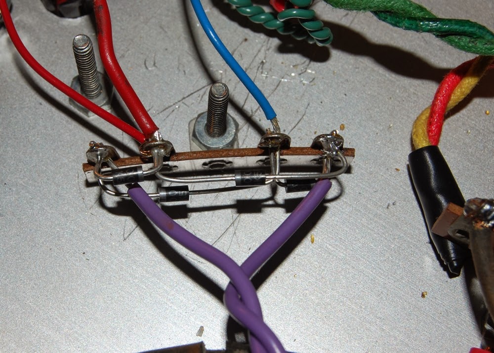
I'd like to note that while the power amplifier stage is pretty much lifted directly from the Kalamazoo, the B+ power supply feeding it is a choked configuration more in line with the 6G15. The single ended amplifier stage feeds an output transformer coupled to a spring reverb tank.
The return from the reverb tank is seen here, direct coupled to the low numbers side of the 12AX7 gain recovery tube. This feeds a tone control connected to the high side of a mix control to output. High number side is a cathode follower dry feed taken from input jack, which drives the low side of the mix control.
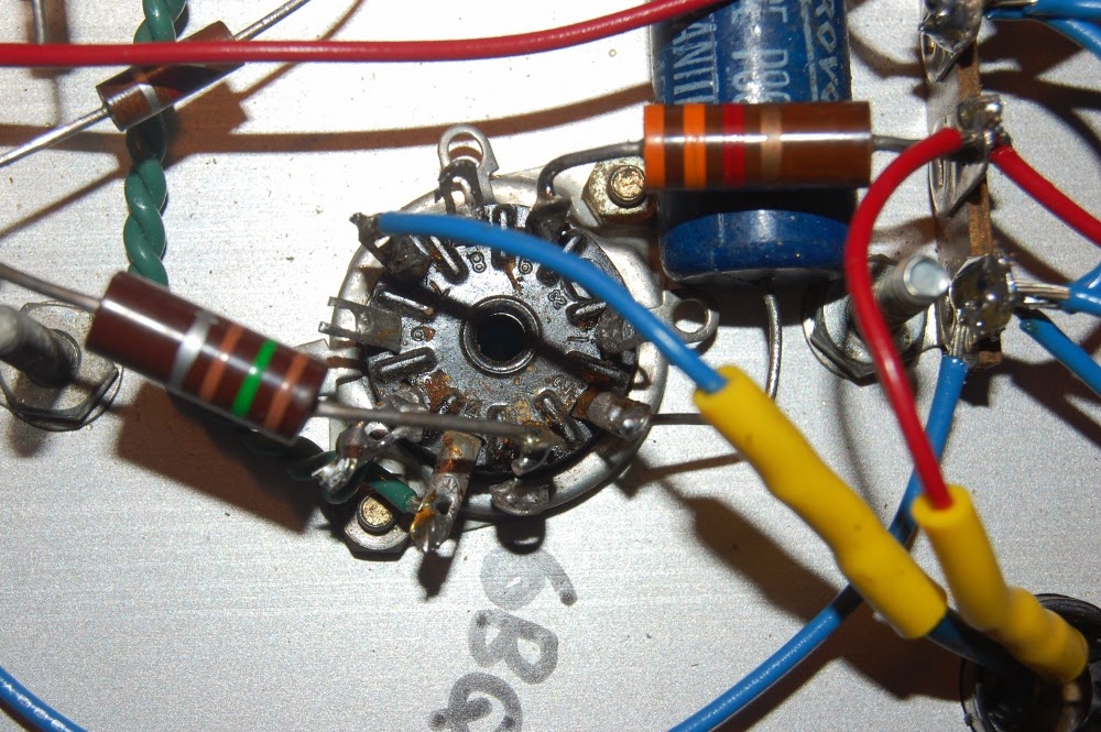
Depicted above is the aforementioned tone and mix controls. Allow me to name off the imbroglio of capacitors, as there is no single photographic vantage point that could make sense of this mess.
The burnt sienna .03@600 CDE to the left is the DC blocking input cap for dry stage. Grid is elevated ~ 100 volts or so, and this fine capacitor is what keeps that off my pickups (or transistors, opamps, transformers, whatever.. outboard spring reverb will see more duty than just guitar).
The cyan/turquoise .1@400 is the DC blocker at dry cathode follower to mix pot (at right).
The .01@400 Sprague Black Cat is my reverb recovery section coupling cap to tone control. I think this should actually be a .1, that's a mistake (see if you can spot two more amidst these pics!) but I guess I'll leave it be unless reverb return sounds too thin.
The black .01 disc cap is the tone cap from control to ground, doing what it can to shunt ALL my signal away since I botched the coupling size.
The domino mica cap is a 500pf coupler from tone wiper to mix. I figured I would double the 6G15 design of 250pf here, because, well, you know, I like a little bass. Hahaha, apparently this was a wasted effort. I'll revisit this later. We're not done yet.

Before anyone pipes up about it, yes, I am aware of capacitive coupling, lead dress and ground loops. Thankfully I'm okay at (read as: used to) working in tight configurations, what with the rework I have in store.
The unit is going to be a controls on face, at bottom type of configuration (ala Marshall heads); so this is the natural finished stance of the chassis. Rear support is not going to be via standoff, it will be supported all sides by wooden runners.
So, with everything more or less squared away I set about the initial slow warm up on a variac. Something, however, was amiss. My voltages were way off, B+ being abnormally low. Concern with a short circuit proved unwarranted. Everything tested out okay, it was just that my B+ leg was reading roughly 10% of expected.
I had tested this transformer prior, and it was concluded to be a ~500 volt center tapped secondary. You know, because I measured it. Having the luxury of an uninstalled identical transformer I conducted the measurement test again on a part out of circuit.
Imagine my surprise when it turned out the high voltage secondary of my chosen power transformer was in fact delivering only ~50 volts across the windings! DECIMAL POINTS MATTER.
Above is an example of finished fitment, tight gap between the tube and chassis. Too tight? I'd probably bevel that on a production unit, but this is not, so..
Anyway, I'm wary about trying to fit enough discrete voltage multiplier stages to make use of the 50 volt center tapped PT work, so I'm thinking about piggybacking another transformer in there, either something with a proper B+ right out of the gate, or a step up I can drive with the 50 volts (I think a 120:24 volt transformer may work nicely here). Sadly, I couldn't find a correct voltage range with identical mounting in my piles, so the fix may wind up being less than visually perfect.
Of course, it'll all be encased in a cabinet anyway. Stay humble!