Showing posts with label power supply. Show all posts

Tuesday, July 31, 2012

I mentioned previously that the Panasonic WJ 545P special effects generator does not supply the necessary power to run the WV-3250 camera through the 10 pin connector. I had, at the time, shrugged this off as the external power supply works just fine.

What I didn't factor in was the element of sync, which happens to be quite crucial for legible video. As it stands, it would appear as if the WJ 545P cannot lock to a composite video signal at the PL-259 input (my abilities as an operator may be at fault here). At any rate, having the option to power the camera at the SEG is enticing, whether or not this will sort out my sync issues remains to be seen.

I believe I've already taken pictures of drilling metal, so let's just skip to the result. +12 volts at roughly 500 mA is fed at pin 10 (pictured with the blue wire sans heat shrink), referenced at pin 9 (behind the blue wire). Naturally the surrounding pins are to be left alone.

Not a whole lot of room to work here.

Here's the result. Some liquid electrical tape that was used to insulate the ends of the disconnected wires, since I have misplaced my heat shrink. The idea was that the end result would be cleaner than electrical tape which can unfurl over time. I wouldn't call this cleaner, so I'll just comfort myself on the permanence aspect.

A bit of heat & melt due to space constraints, could have been worse.

So there you have it, DC power input for camera channel 1. Since the SEG supports only two channels simultaneously I didn't see the point in modifying more than one input, as I have multiple SEGs that will cascade into one another (forming a loop if I choose) and the power supplies I have earmarked won't support more than a single camera. I'll just allocate channel 1 as a powered input for each.

Tuesday, November 01, 2011

Tore apart the Ratelco 24 volt battery charger in order to assemble a very primitive unregulated power supply for the stepper motors of the CNC project.

Essentially this entailed ripping the mains transformer, rectifier block and caps out of the supply, leaving all the current sensing & regulation for the parts bin. The bay in the frame is 5U tall, and the Ratelco was 6U tall, felt good to tear it apart.

I recall reading that a rusty transformer has one foot in the grave and another on a banana peel. That's just the sort of amusing imagery it takes to stick something in my mind for years. Not that I'm going to adhere to such a sentiment, mind you. I fully agree that stopping further advance of rust is a good idea, in so far as stopping the advance of rust is reasonably possible at any rate. After embarking on a read of Practical Transformer Winding I was reminded that the oxide layer of rust performs much the same electrical function as the laminate varnish insulation, and while infinite resistance is highly unlikely, the resistance should be high enough to effectively isolate one laminate in the stack from the next - so long as moisture is removed from the equation. So, next time I photograph this thing it will have a fresh coat of paint on it.

Here's a rough layout of the PSU, I will bolt down the base plate before assembly. The 1N1188 bolt on DO-5 diodes purport to be good for 35 amps, I don't see the four motors pulling that even if each is under full driven load at the same moment, so I may leave them even though the heat sink will be hot (electrically) which is something I'm not too excited about. Still on the drawing board there.

There are a few windings here that I don't have a direct application for, time will tell if they'll serve a purpose. The original circuit was designated 24 volts, it provided roughly 28 volts unloaded, if I can boost/buck to bring it up to 30 or so I'll still be well under the 40 volt cap of the 64000 uF capacitors.

I think this served as current sensing in the battery charger, I'm still contemplating applications. There's a distinct lack of standard objects for scale reference in this post, sorry.

Friday, June 03, 2011

Another broken EC-Apparatus high voltage power supply!


The 'stickers' up top say "OK to use 8/25/94" and "DEAD 2/3/97". Took it 14 years to rotate into the scrap pile. The AC cord has been cut. I understand the motivation to cut power cords; it remains annoying.


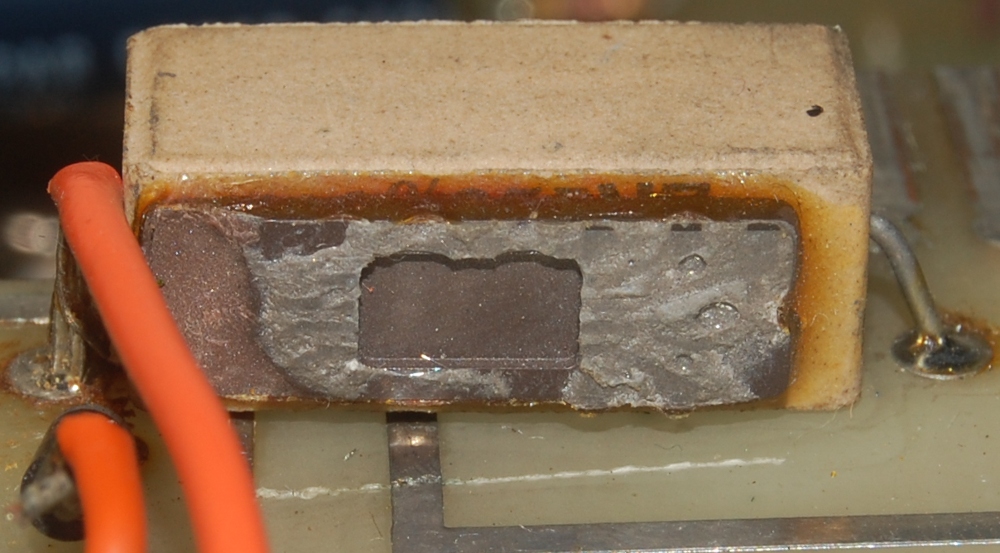
On cracking the shell, this was the first sight to greet me.


I must admit, I'm having a little difficulty identifying this part. Initially it struck me as a wirewound resistor, but the remains don't exhibit the centralized burn characteristics I'd expect to see from a resistor. Additionally, this part appears to have let loose in a rather prompt manner as opposed to a slow and steady heat build up.

Then there is the ochre build up at center band, which appears to be an original compound as opposed to corrosion products. Electrolyte perhaps? Yet the plate structure, if this is a cap, seems wrong to me, and an electrolytic cap of this dimension sitting on a ladder in the filtering section of a 2000 volt power supply makes no sense either.


Whatever it was, it clearly was not up to the task it was asked to do.


The unit over-all looks pretty service friendly, just peeking above the stack of 47u 450v is a blue backplane connector which allowed removal of the board containing most of the sophisticated circuitry.


Of course, that circuit board offers a mystery of its own.


I should give a big fat sandfilled power resistor a shot in lieu of a 3000-3500 ppm/K tempco on a supermatched pair! That would probably cause a quiver or two in the synthesizer community.

My initial response to this structure was, as is known in the internet parlance, WTF?!

But wait, it gets better:


This is apparently the stock part having failed.

As usual, once the amusement has died down a bit, I stopped associating this structure with a similarly built (though altogether different) structure, and reason that the 16 pin DIP package may not be an IC, but a thermistor housed in a DIP package as part of the current regulation circuit.

I remain unsure. Cool enclosure though, perhaps I will have a go at repurposing it to house a supply that offers a more immediately useful range of voltages, eventually.

Monday, March 28, 2011

No work surfaces make me cranky. I'm still on the Intersound Mini-Six. My work surface for this particular project up to this point has been, I shit you not, a Hallicrafters S-53 sitting on top of the Lafayette U-50 standing on its side.


Here's an overlay of the circuit components I pulled out of the malfunctioning negative side of the +/- 12 volt power supply.


Here's a pulled trace from extracting the master volume control, not really an impediment, just annoying.

In plotting my approach to repair this unit, I've opted for simple regulation in the power supply. A regulator, instead of a discrete circuit. I'm going to learn what I can from the original circuit, but as a matter of course I'm taking the easy way out for now.


Turns out I didn't have TO-92 regulators on hand either, so the legs of a TO-220 are trimmed to fit.


Next step should be obvious..

So, I slapped a voltage regulator in and fired it up.

Lo and behold, there is now a negative voltage! However, it is less than 12 volts; and establishing a negative rail has pulled the positive rail down by several volts as well.

It was at this point that the ludicrousness of sitting on a box on top of a milk crate while working on a "table" that essentially boils down to a balancing act really sunk in. All tinkering is in stand-by while I sort out space issues.

Take care of your work-bench.

Friday, March 18, 2011

Were TO-92 voltage regulators difficult to source in the late 1970s?


This 2N4403 is in the regulator hotseat with roughly -22 volts at collector, -16 at base and nothing at emitter. The 2N4401 on the positive rail shows much more reasonable voltages of 13.4, 12.6 and 11.9 respectively.


I'd like to know who drew arrows on this unit, and why. The arrow shown is pointing at the leg on which there should be voltage but is not.


More cryptic hints topside.


I'm tempted to gut the regulator sections and populate with 7812/7912.

Thursday, January 06, 2011

Inching forward with the CNC project, my screws and some hardware have arrived.


Here's a quick mock-up of my X axis, well, hardly a mock-up, but I digress. Framework and data handling aside, these are the important parts.

X axis is to ride on THK linear bearings, driven by a Pacific Scientific Powermax II stacked stepper turning a screw, powered through a GeckoDrive G201X which will receive commands ala dedicated desktop PC running Ubuntu/EMC2. Having all these components laid out in front of me means I really need to address the power supply sooner than later (now).


Front and center sits 112 pounds of power supply, waiting for me to lug it to the bench.


It's only after executing that little juggling operation that I remember this is the unit with a faulty breaker on the DC side and what I'm really after is the 107 pound power supply that was sitting next to it.


After a brief inspection confirming that the power transformer is strapped for 120 volts and nothing is visibly leaking, bulging or dead inside the case, I fire it up. The hum of operation borders on a buzz, but no smoke or sparks thus far... good.


There's a standard cassette tape at upper right for scale.

There's a point of concern with this PSU, the DC breaker. I've gathered that it's inadvisable to to switch the DC side of the power at the drivers, as they will face back EMF from the motors which can burn them up, setting me back replacement costs on up to four G201X, which isn't something I'm interested in.

The supplies are also tailored to battery charging, which has a different set of operational parameters than driving motors. My Y axis will have two motors working in hard sync to move each leg of the gantry, the two stacks of each motor are going to be wired in parallel, offering a path rated at 7 amps per motor. So the last thing I want is some battery configured current sniffer to crowbar output voltage when I most need it.

In short, I came to the realization last night that my best tactic is to gut the logic/regulator portion of the power supply, reconfiguring it into a primitive rectified DC beast, which, as I understand it, is best for this brute force application to begin with. I guess I could have stayed with the heavier supply after all.

Monday, December 13, 2010

Here we have another variable power supply, an EC Apparatus Variable DC Supply that is a touch worse for wear.


My guess is that this either took a spill from say, the back of a truck, or someone intentionally did this when they misapplied power to themselves. I'm still surprised that the glass on the meter didn't get punched out.


Since I've already got a couple variable DC bench supplies my plan of action was to gut this unit for parts and move on with my life, but something is different here.


This is wired in the classic half wave voltage doubler configuration. The caps are each 80mf at 500V, and the diode strings are built from three cascading 1N1449 diodes, which are spec'd at 400 PIV each.

So, what I have here professes to be a trashed high voltage DC supply, which is another matter altogether.


I question the wisdom of building a power supply in a 17 gauge aluminium enclosure, this former corner sides with me. I'm under the impression that the point of impact was at the 12 o'clock position of the variac dial, and that most of the damage stems from the base (on which over 7 pounds of iron reside) having its momentum arrested through the squish of the upper 17ga shroud. The corner pictured above is situated at the opposite end of the suspected impact, so the distortions would be of a pulling nature at this point.


Still, a variable DC supply that will power tube circuits is something I've needed for a while, so I'll undertake the repair process, begrudgingly within the original enclosure. I'll try to avoid dropping it from heights or using it to hold up my car though.

Tuesday, November 30, 2010

Another variac/variable DC supply for the bench, this one shows the mark of DIY so I figure I should check it out before using it.


We have no need of sleek, streamlined bullshit here.


I begin to wonder if this wasn't completely thrown together by someone, as the 200 VA 24 volt step down transformer (in black) and and huge choke are designed to carry current far in excess of what the 2.25 amp autotransformer can deliver (2.25 amps being its design limit no matter what voltage it delivers).


The rectifier for the DC side illustrates gargantuan over design..


..while the profusion of electrical tape and some of the taps illustrate haste. This thing is certainly a cobbler hammered out on some freaks workbench, should be right at home once I dress the bare wires and introduce it to some compressed air.


Here's a nice hook-up diagram for a variable autotransformer. Wall voltage is wired across either 1 and 2 (allowing a 0-120 volt range) or 1 and 4 (allowing a step up to 0-132 volt range) actual voltages are going to hinge what you have at the wall, the 1-2 = 100% and 1-4 = 110%. Output is at terminal #3 (variable hot) and terminal #1 (neutral).


Here's a shot of the markings on the choke, mainly because I like the distortions incurred by taking a shot through the perforated steel.