Showing posts with label enclosure. Show all posts

Monday, December 09, 2013

Our temperate region was hit with an abnormally cold storm, derailing my plan to drive across town and use appropriate power tools to fabricate an enclosure for the reverb amplifier. I was actually toying with the idea to clamp a temporary table to my radial arm saw project (future instalment) when I came across an old Bach trumpet case I had salvaged from a pile of enclosures that were slated for a stop in a dumpster.

According to the reverb pan, this case will work out just fine.

Gutting it was not nuisance free.

The glued in monkey fur (remaining after I peeled the fabric backing away, which was a chore in itself) gave me ample opportunity to oil up my language.

Ultimately, once the fire hazard levels of fluff were removed the case continued to show promise. The area to the right where the shim block is will be filled with the B+ transformer I'm adding to the party.

Before I get that far, however, I want to address the incorrect capacitor I noticed the last time I posted, because the additional transformer is too large to mount to the chassis and performing work with a tethered chunk of iron is going to push the nuisance aspect a bit. Here I've pulled the 0.01 Black Cat and have eased a 0.1 Aerovox Duranite into the slot.

Access to the leg of the potentiometer necessitated the temporary displacement of the Domino cap, here everything is in position and ready for soldering.

Once the potentiometer assembly was buttoned back up it was time to address connection to plate leg of the tube socket, however, the longer package in the 0.1 cap put the B+ a little too close to the grounded screw for my comfort.

Tasteful application of brute force corrected the interference fit.

Nice round bend taking up the slack.

With the chassis sorted it was time to address the previously discovered deficiency in the higher voltage secondary of my installed transformer. I had toyed with the idea of putting a step up transformer across the 50 volt CT winding, but tests indicated that it was overburdening the 50 volt winding, so that plan was scuttled and this transformer was brought in, which provides roughly 200 volts DC once rectified, which is plenty for me.
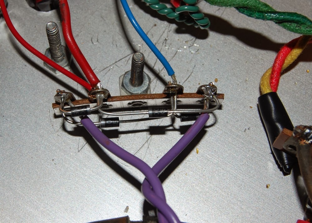
I got to fill in the empty eyelet with a ground reference due to no center tap on the transformer.

With my car still snowed in (we reached -10F/-23C and the old moisture bearing door seals quite literally have frozen this car into a solid shell, though I am certain the aircooled motor would fire right up - if only I could get inside to operate the car) I decide to hand carve the enclosure.

Naturally, the larger knife I would normally reach for in this instance is currently TRAPPED INSIDE MY CAR, so I had a go with an old box knife...

...which resulted in many shavings.

I think in the end it will all be worth it though.

Monday, February 20, 2012

Grabbed some weathered & rusty sheet rems today. Only proper to put the brake through its paces.

1st box bent. 2x4x0.75", seems a fitting enclosure to a LPB-1 clone, really can't have too many of those around. I'm really not trying to embrace the steam-punk look, but I'm not NOT trying to look like steam-punk enough to deny that knob, I foresee occasions, due largely in part to my methods and materials, that the steam-punk aesthetic will be a basis for comparison. In much the same way my oils are steeped in comparison to Jackson Pollock. Best to not be bothered with it.

1st box has some pretty organic lines, the corner stresses do contribute to this.

Pre-punching the corners with a small drill on the second box really hit the spot.

The second box may house the SN Voice I haven't completed in far too long. The variety of knobs are there to fuel my thinking in regards to which way I want to go. If I had eleven of the one at lower right I would be set! My line of thinking is to route a wood plank base to drop the metal enclosure on, end ears will be cut longer in the (near stage) future to sink into slots cut into the wood, which will tie into hardware holding everything together.

Measures in at roughly 9.5x4x1". I did take to hammering a bit which takes away a bit from the crispness of the lines. Once I get the primary bends sorted I will work in tab bends to clean everything up, that said, I am liking the Mad Max look..

I wound up with enough metal stock to bang out roughly sixteen of the smaller enclosure and eight of the larger for $4.50 US. Economical build tactics.

Not a whole lot going on in here yet. I will be experimenting with double bent sides shortly.

Looks like I have a good reason to really start thinking about a DIY spot welder. I have some iron that could probably be rewound to provide for the sort of current required (yes, I realise that rust has to go before that's really a doable thing).

Another design tactic I need to sort out is how to retain the patina without the mess. I like the rust...

I can fully appreciate why others may not.

Tuesday, December 14, 2010

I'm currently at odds with my organization program down at the lab. I have a box of switches that is eluding me, and completed projects are starting to back up because of it. I figure I may as well add the EC power supply to the pile.


First step was to remove all components and hardware from the upper shroud. I posed it here with some of the objects I will be using to realign the sheet metal, notably absent: hammer, perhaps the most important tool of all. Okay, that tool is the mind, I'm still a bit miffed that the hammer wandered off during the photo shoot.


My initial idea of gently clamping stuff into shape was rapidly undermined by an array of deficiencies in the tool department. Seeing as how the project was under way on the living room floor and my ability to make new tools involved going across town, I reassessed my approach.


Roughing in the general shape by hand is satisfying, 17ga metal offers minimal resistance.


Shaping the corner is as easy as clamping in some appropriate backing material and tickling the outside edge with a hammer.


I'm over-all satisfied with the shape. It is no secret I'm fine with rough looking equipment so long as it is functional.


I'm pretty sure the front panel controls can be mounted now, free of interference.


All shaping after that clamped corner was a hammer and the small block held by hand.


Raises arm, shields eyes..


TAP


And so, rebuilding begins. Stymied by the lack of a power switch (the original is in many pieces) I occupy myself mapping the guts of this unit, to assist in understanding and potential troubleshooting down the road. It's not without a few points of concern.


When powered, the entire rotating assembly here is electrically hot. Since the structural integrity of the case isn't stellar, I'll have to refrain from placing heavy objects on the conveniently flat surface the top of the case provides.

There's also only a fuse in line with secondary side of the variac. I plan on placing a primary side fuse in the opening that carried the variable AC output jack, since I don't need another variac.

Now, to locate my switches so I can reassemble this, repair the Peavey EQ-27, a delay, and something else that's slipping my mind at the moment..