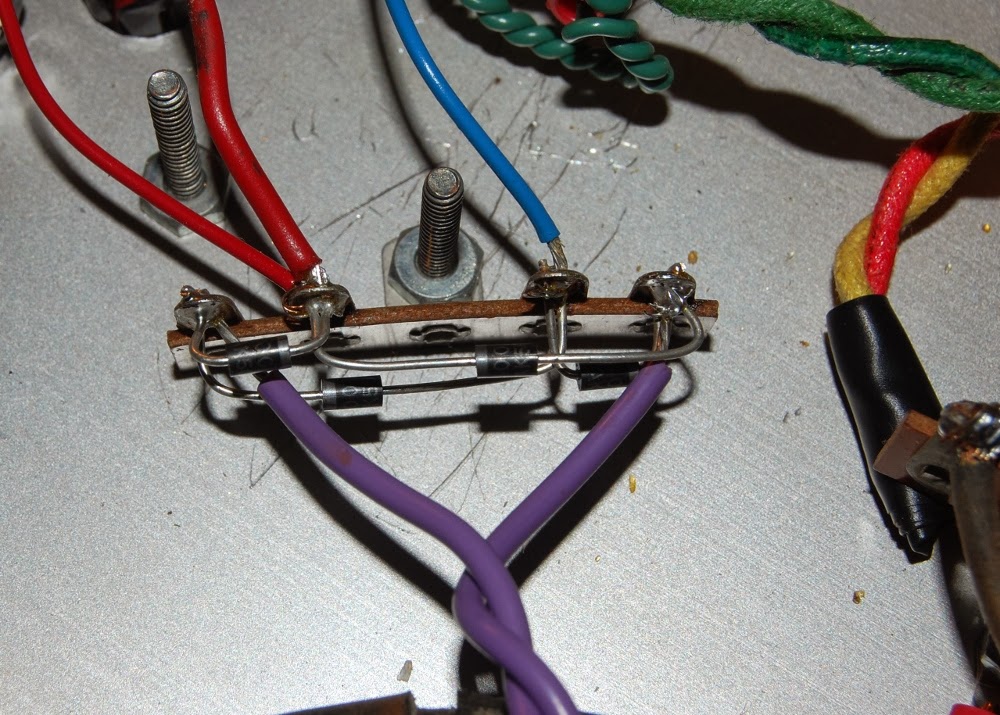
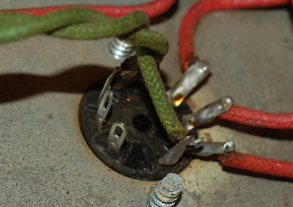
Showing posts with label modification. Show all posts

Friday, April 11, 2014

Drilled out the rivets securing the back panel of the IRP Voicematic to allow a bit of useful modification.

It's a little difficult to discern here, but there's an uninsulated wire in between the black and white twisted pair along the backplane buss. According to my scope, the bare wire is the audio feed line from the independent cards to the master summing section. Visible are my sloppily hand aligned holes.

The idea here is that since all the cards output direct to this buss wire, I can get away with installing interrupting jacks (Switchcraft 12A) so that the card feeds the tip directly, which is shunted to the combined buss when nothing is plugged into the jack. I've opted to only go so far as metal work on the 11/12 hole, as I don't have a card for that pair. So yeah, I'm leaving a HOLE in the case. Never know when it might come in handy.

Functional, though the recovery amplifier provides for considerable gain, so direct patching the two input card has a much lower level than what is available at transformer output. I guess that's what booster pedals are for.. HAHA.

Monday, December 09, 2013

Our temperate region was hit with an abnormally cold storm, derailing my plan to drive across town and use appropriate power tools to fabricate an enclosure for the reverb amplifier. I was actually toying with the idea to clamp a temporary table to my radial arm saw project (future instalment) when I came across an old Bach trumpet case I had salvaged from a pile of enclosures that were slated for a stop in a dumpster.

According to the reverb pan, this case will work out just fine.

Gutting it was not nuisance free.

The glued in monkey fur (remaining after I peeled the fabric backing away, which was a chore in itself) gave me ample opportunity to oil up my language.

Ultimately, once the fire hazard levels of fluff were removed the case continued to show promise. The area to the right where the shim block is will be filled with the B+ transformer I'm adding to the party.

Before I get that far, however, I want to address the incorrect capacitor I noticed the last time I posted, because the additional transformer is too large to mount to the chassis and performing work with a tethered chunk of iron is going to push the nuisance aspect a bit. Here I've pulled the 0.01 Black Cat and have eased a 0.1 Aerovox Duranite into the slot.

Access to the leg of the potentiometer necessitated the temporary displacement of the Domino cap, here everything is in position and ready for soldering.

Once the potentiometer assembly was buttoned back up it was time to address connection to plate leg of the tube socket, however, the longer package in the 0.1 cap put the B+ a little too close to the grounded screw for my comfort.

Tasteful application of brute force corrected the interference fit.

Nice round bend taking up the slack.

With the chassis sorted it was time to address the previously discovered deficiency in the higher voltage secondary of my installed transformer. I had toyed with the idea of putting a step up transformer across the 50 volt CT winding, but tests indicated that it was overburdening the 50 volt winding, so that plan was scuttled and this transformer was brought in, which provides roughly 200 volts DC once rectified, which is plenty for me.

I got to fill in the empty eyelet with a ground reference due to no center tap on the transformer.

With my car still snowed in (we reached -10F/-23C and the old moisture bearing door seals quite literally have frozen this car into a solid shell, though I am certain the aircooled motor would fire right up - if only I could get inside to operate the car) I decide to hand carve the enclosure.

Naturally, the larger knife I would normally reach for in this instance is currently TRAPPED INSIDE MY CAR, so I had a go with an old box knife...

...which resulted in many shavings.

I think in the end it will all be worth it though.

Sunday, January 20, 2013

I was recapping my Roland SMX-880 a while back and got hung up on the fact that I hadn't observed the fact that the 10uf electrolytic at input jack was a bipolar. Quick test confirmed that this cap is situated in line with the signal, it is the first thing the signal hits.

I wasn't about to put some polarized cap there, so the unit was set aside to await a parts order. In the meantime I read a bit of opinion on the internet I found agreeable: "The best sounding capacitor is a piece of wire".

Brilliant. Upper right corner, I hadn't any plans to subject it to DC anyway.

Sunday, December 23, 2012

Okay, I've known about the Otari XLR pin 3 hot configuration for quite some time now, but in practice I'd never run into a catastrophic failure because of it (that is to say, I was able to record and playback audio on the 2 track machine with little issue). Therefore, that bit of information sunk into the dusty corners of my mind where it was wholly ignored. Of course, all that free riding came to a screeching halt once the Autogram AC-8 was planted in the audio control trunk. See, in my wiring up the output I included unbalanced 1/4" phone plugs which were at one point normalled to the monitor amplifier.

So, when I connected the pin 3 hot, pin 2 ground configuration of the Otari to the pin 2 hot pin 3 neutral (actually earth referenced thanks to my inclusion of unbalanced 1/4") configuration of the mixer output, a whole lot of nothing happened. Nothing to the tune of even killing the monitor feed to the amplifier.

I had entered into really easy diagnostics, unplug cable = sound, plug it in = zilch. So, with a nod to the widely published pin 2/3 issue, I built a pair of XLR cables with pins 2 & 3 swapped. Solved. Of course, at this point I recall a few months previous while I am working on the basket case MX5050-8 and can't get any channel response out of it, which, at that point was a step backward but given the hard life the machine has had I place it closer to the parts bin. Why yes, I had been feeding it audio from the Autogram while failing to get signal, it was just prior to the monitor amp feed modification.

So, the 2/3 swap XLR cables worked here too. I was able to commit signal to tape and playback (on conventional XLR), and it sounded good. So, my options now are to make another 6 pin swap XLR cables, or just modify the machine to reflect pin 2 hot. Ready to cut traces and jumper stuff at board level, I was met with this magnificent sight. Build six special purpose cables, or simply rewire 16 connectors?

Easy decision.

I did this, from poor placement in a room (that gets gear hauled in and out of)...

..and this. Very preliminary internet searches do not favor the notion that this is an easy & standard current production off the shelf part. Since the switch still works I think I may drill a small pilot hole in the lever portion and turn down a bit of small bar stock to have an end pin, then epoxy the new arm in place. Worse case I'll still have to find a replacement switch.

Since this machine got hammered the interior finds include stuff like this, from the side panels.

Tuesday, July 31, 2012

I mentioned previously that the Panasonic WJ 545P special effects generator does not supply the necessary power to run the WV-3250 camera through the 10 pin connector. I had, at the time, shrugged this off as the external power supply works just fine.

What I didn't factor in was the element of sync, which happens to be quite crucial for legible video. As it stands, it would appear as if the WJ 545P cannot lock to a composite video signal at the PL-259 input (my abilities as an operator may be at fault here). At any rate, having the option to power the camera at the SEG is enticing, whether or not this will sort out my sync issues remains to be seen.

I believe I've already taken pictures of drilling metal, so let's just skip to the result. +12 volts at roughly 500 mA is fed at pin 10 (pictured with the blue wire sans heat shrink), referenced at pin 9 (behind the blue wire). Naturally the surrounding pins are to be left alone.

Not a whole lot of room to work here.

Here's the result. Some liquid electrical tape that was used to insulate the ends of the disconnected wires, since I have misplaced my heat shrink. The idea was that the end result would be cleaner than electrical tape which can unfurl over time. I wouldn't call this cleaner, so I'll just comfort myself on the permanence aspect.

A bit of heat & melt due to space constraints, could have been worse.

So there you have it, DC power input for camera channel 1. Since the SEG supports only two channels simultaneously I didn't see the point in modifying more than one input, as I have multiple SEGs that will cascade into one another (forming a loop if I choose) and the power supplies I have earmarked won't support more than a single camera. I'll just allocate channel 1 as a powered input for each.

Tuesday, May 08, 2012

I purchased a Sony MX-6S a while back & seeing as how I queuing up to play a somewhat stripped down minimalist set last Sunday I found it high time to bring it into the realm of usefulness.

The MX-6S is a passive resistance mixer originally bearing three RCA connectors feeding the AUX channels & three 1/8th inch monophonic miniature jacks feeding the MIC channels. The center MIC/AUX channel is switchable to the destination of output channel 1 or 2, which took the form of ~2 foot pigtails terminating in 1/8th inch plugs.

I can begrudgingly support both RCA & 1/8th inch miniature in the studio; pigtails, however, have to go & since I've going to be in there already...

Removal of existing output wires is as simple as desoldering the points on this circuit board (upper grey wire shown here is channel 2 output, whereas channel 1 was connected to the fifth & third notch at the lower right of PCB) and pulling the wire out. Pulling the wire was further simplified through studied application of snips.

Rather than destroy the 3x RCA jacks to harvest the phenolic mounting board, I fabricated a new one out of mild steel to mount the 1/4 inch phone jacks, the original MIC connectors simply unscrewed to allow drilling the phenolic out to accept the larger jack. Further drilling was required at outputs. The MIC inputs are a rat's whisker away from an interference fit with the switch bracket, this probably wouldn't have been a problem if I hadn't run out of open frame jacks.

Output is further modified with a switching jack that will route channel 2 output to channel 1 if a cable is not plugged into channel 2.

Much better. The two input banks are different from one another: AUX is set up for line level with a 100K log as volume, MIC was originally terminated across a 560 ohm resistor feeding a 5K log as volume. This is equivalent to different gain structures when fed by something that is not loaded down on the MIC input (I opted to not reinstall the 560 ohm load resistor) in my very limited experimentation I find the higher impedance inputs far easier to control.

Worked like a champ, I expect it will see a lot more use now.

Sunday, April 22, 2012

Yesterday saw a little progress on the modification of the Traynor YBA3 Custom Special

The amp had been red-plating. As it turns out, this 150K dropping resistor (the bias supply is fed from the full high voltage B+ secondary, knocked down and separately rectified) had drifted up to 234K, and the 15K between cathodes of the bias smoothing capacitors had been replaced with a 45K flame proof, effectively tamping the available bias voltage down to useless levels. Hence, a bit too much current flow through the tubes.

Since this amp is purposed to be a player, and is already far from pristine, I'm comfortable with performing non-reversible modifications on it. To facilitate an adjustable per tube bias tap I undid the original bias feed at output tube grids (the connection above the nut) and removed the two 220K resistors. Full bias is now delivered from the adjustment pot to pin 1 of output tube and a 270K half watt carbon film resistor connects pin 1 (G3) to pin 5 (G1).

I also plucked the 1K5 grid resistors flanking the yellow 0.1 @ 600 coupling caps. As you may remember, I had questioned the lop sided approach to the inner and outer pairs of output tubes. I figure this is as good a place as any to test the effects of resistor distortion, so I planted 1/4 watt 1K6 carbon comps on every output tube signal grid. I realize there's negligible DC drop at this point, but I had the resistors on hand, so...

In order to minimize the flying parts construction, this modification entailed physically switching the alignment of signal path at the post phase inverter coupling caps seen here. Since I had already gutted everything on the "upper" row, switch over was easy. This move the DC bearing phase inverted signal back over the circuit, but the AC feed to the output section is a straight shot as opposed to incredibly long flying leads. So, I'm cautiously optimistic that I haven't destabilized the amplifier do to messing with lead dress (and I'll know where to start looking if instability is a problem).

I did have to create another chassis ground connection, the preparation of which involved removing patina with hardened steel (a chunk of razor blade). Metallic dust was removed by magnet. I took some close up pictures, but the razor thin depth of field didn't do me any favors. So those pics are not included.

One 100 watt soldering iron later.

Here's a sidelong shot of the modified output section before I reconnected the feedback tap at output. 2 watt 560 ohm screen resistors were also added, this is on top of 1K drop on the screen supply, which may be adjusted depending on performance seeing as how the 1K is made up of two 500 ohm in series.

The white cloth wire connects tube cathode to test point, which is connected to ground via a 1 ohm resistor.

I've done uglier work. I'm not elated about the aesthetic appearance of the screen buss (upper yellow wire) and the eyelet connections ofr the bias supply are a bit congested with the trunks of red & white wires, but over all there remains room to work and everything is electrically sound.

Another angle on the same stuff.

Over all guts. The ten footer view isn't half bad. I'd like to belt the three Sprague Atoms on the left down, but construction grade double stick tape will have to work for now (they've not given me any problems).

In order to give AC mains and the body of one of the 10K pots a comfortable berth, I had to rotate the fuse holder. Since the chassis is punched with a D hole, this entailed a pass with the file. The scuffs on the rear panel being a typical rookie mistake (I'm embracing the scratch & dent look on this amp) moving along...

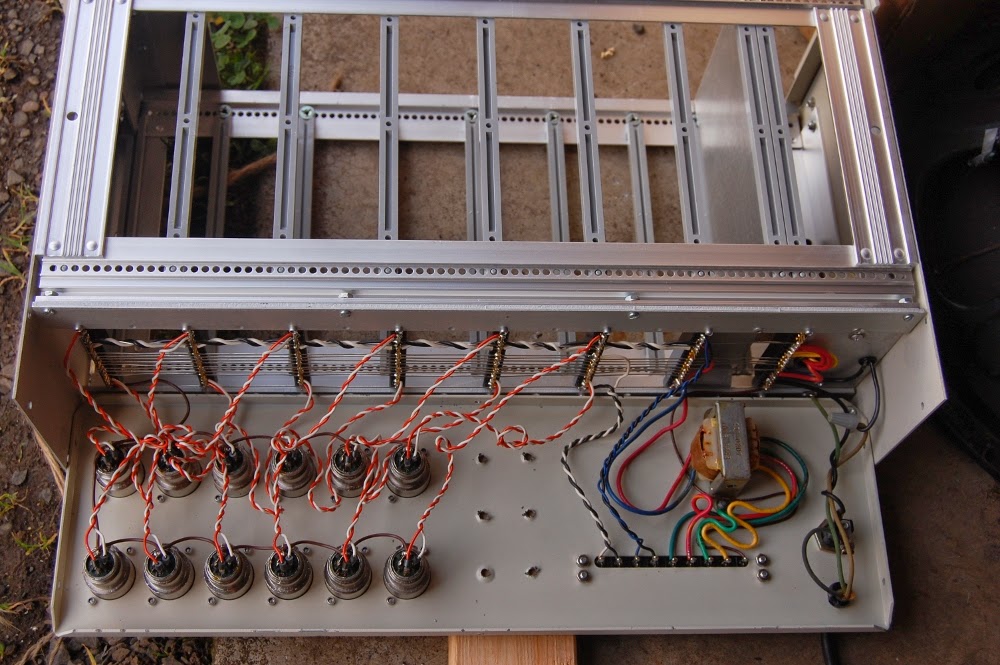
Here's the finished set up. I slapped in a matching set of 10K pots since the picture of the mock up (THANKS DAN!). However, I haven't yet had the opportunity to test this, since my benchtop variac suddenly has a failed outlet and the other variac at hand has an intermittent short that was swinging the ammeter once it hit 50 volts.

So yeah, I expect some more variac discussion on the horizon.
Monday, April 16, 2012

Multi-tasking amounts to a slow haul overall.

Punched a few holes in the Traynor YBA3 to support per tube bias trim with measurement while the amp is up and running.

Magnets assist in the collection of oily shavings.

Finished looking from the outside, still not complete from the inside. As wired shots next.

Monday, April 02, 2012

The Traynor YBA3 Custom Special is queued up on the bench to receive a little love and modification.

It would appear that mine is an early version of transition from 7027 to 6CA7. Parts date to early 1969.

In thumbing through online pictures of YBA3 guts I have not seen this, but short of carbon dating the solder it really looks original to me. I added the knob since I like non conductive stuff to grab hold of when faced with amp guts. The mystery was what function this pot served, since it has nothing to do with the bias section..

Above is the first (or earliest I can find) revision circuit amplifier: non master volume, choke in the power supply, fixed resistor bias and 7027 output tubes. The aforementioned 892K mystery pot is high lighted in red, the 68K & 470 ohm resistors tied directly to the wiper. The only other real departure this amp has from the above schematic is in blue, as in that part can be omitted in its entirety and the following output section is referenced.

I elected to mark up a later schematic in lieu of the early 6CA7/EL34 circuit due to the cleaner scan (sadly my amp does not have its own schematic in the lid), the primary difference between the earlier and later sections are R51 & 52 - high lighted in red, those 1K5 grid resistors are not and never have been in this amp, however the matching (green) 1K5 feeding the grid of the "secondary" (outer) pair of output tubes IS in place (as seen on earlier schematic).

Also unique to the outermost tubes of the PP quartet is a 47 ohm 2 watt screen resistor (inner green). I'd been scratching my head about this, wondering why the circuit is different between the inner and outer pairs of output tubes when it dawned on me that the grid resistor might shed enough negative bias that the screen resistor is necessary to retain over all balance?

That line of inquiry is somewhat moot. I'm going to be installing screen grid resistors on each and every output tube. In addition to the grid resistors I plan on installing individual bias branches per tube (replacing the yellow stretch & pulling the bias supply feeding pin 1) with banana access to 1 ohm cathode resistors.

Orange overvoltage protection circuit has been removed, though I would consider replacing it if I had the correct parts.

Blue output section places speaker loads in series. I'm thinking of changing this to a standard parallel wiring.

There's also the little matter of an open triode to exploit.