Sunday, December 23, 2012

Okay, I've known about the Otari XLR pin 3 hot configuration for quite some time now, but in practice I'd never run into a catastrophic failure because of it (that is to say, I was able to record and playback audio on the 2 track machine with little issue). Therefore, that bit of information sunk into the dusty corners of my mind where it was wholly ignored. Of course, all that free riding came to a screeching halt once the Autogram AC-8 was planted in the audio control trunk. See, in my wiring up the output I included unbalanced 1/4" phone plugs which were at one point normalled to the monitor amplifier.

So, when I connected the pin 3 hot, pin 2 ground configuration of the Otari to the pin 2 hot pin 3 neutral (actually earth referenced thanks to my inclusion of unbalanced 1/4") configuration of the mixer output, a whole lot of nothing happened. Nothing to the tune of even killing the monitor feed to the amplifier.

I had entered into really easy diagnostics, unplug cable = sound, plug it in = zilch. So, with a nod to the widely published pin 2/3 issue, I built a pair of XLR cables with pins 2 & 3 swapped. Solved. Of course, at this point I recall a few months previous while I am working on the basket case MX5050-8 and can't get any channel response out of it, which, at that point was a step backward but given the hard life the machine has had I place it closer to the parts bin. Why yes, I had been feeding it audio from the Autogram while failing to get signal, it was just prior to the monitor amp feed modification.

So, the 2/3 swap XLR cables worked here too. I was able to commit signal to tape and playback (on conventional XLR), and it sounded good. So, my options now are to make another 6 pin swap XLR cables, or just modify the machine to reflect pin 2 hot. Ready to cut traces and jumper stuff at board level, I was met with this magnificent sight. Build six special purpose cables, or simply rewire 16 connectors?

Easy decision.

I did this, from poor placement in a room (that gets gear hauled in and out of)...

..and this. Very preliminary internet searches do not favor the notion that this is an easy & standard current production off the shelf part. Since the switch still works I think I may drill a small pilot hole in the lever portion and turn down a bit of small bar stock to have an end pin, then epoxy the new arm in place. Worse case I'll still have to find a replacement switch.

Since this machine got hammered the interior finds include stuff like this, from the side panels.

Saturday, December 22, 2012

Took in the new Baktun with some long overdue recording yesterday.

I'm still not clear of the underbrush in regards to the Otari, but it performed very well on tracks 3 & 4 yesterday, proving that continued hammering is warranted. But, this post is not about the tape machine.. in setting up to record I decided to utilize the long neglected Eventide H3000. I discovered forthwith the fact that the soft keys had entered into the realm of unresponsiveness, robbing me of the ability to edit patches and really use the instrument.

That simply would not do. Guts up.

I have some number of gaps in memory, as in the manual references patch programs at certain numbers that for all intents are inaccessible on this machine. Seeing as how I can still construct whatever I want, I'm ignoring that right now. The H3000 sounds good, and is a capable effector (honestly, if the digital vs analog sound quality debate comes up I'll point to this thing as the STFU card, and I am of analog bias). Anyway, I'm not here to talk about the selective memory either.

I just find it interesting that ROM doesn't fit the socket, and am curious about the empty socket to the right. No matter...

When I bought this it was inoperable. It would power up briefly, then the relays would click into bypass and everything dimmed out. The cause of this was the plug depicted here. Addressing conductivity at this connector brought the unit back to life. So yeah, I'm always on the lookout for rack mount Eventide gear that exhibits those symptoms, even though I just gave away the thousand dollar fix.

Anyway, back to the soft keys. Pull the bottom cover and this is the access. Spray liberally with residue free contact cleaner while tapping the switch. Allow complete evaporation, reassemble & enjoy your fully responsive instrument!

Thursday, November 15, 2012

I've been fine tuning the Autogram AC-8, I had pulled the MXA-1 & LA-1 modules from the AC-6, as there was pronounced imbalance between the right & left sides of the audio feed. A little bit of swapping sorted this out. Mind you, this tuning had occurred while the studio monitoring system was piggybacked on the program output feed.

Such a configuration is less than ideal for a few reasons, being able to monitor the audition channel for one. Having access to a control room volume other than amplifier input trim or mix levels is pretty handy as well.

The problem was that while input/output feeds all terminate to barrier strips for easy interfacing with the rest of world, the monitor feed of the AC-8 was internally routed to onboard amplifier sections, so the original monitor connections are post amplifier speaker feeds. While I have few reservations on the standard of quality that Autogram put forth into this unit, I've already got a monitoring set up slated for use and have no interest whatsoever in using the MA-1 monitor amplifier between my ears and the work.

Fortunately the monitor modules are built on standard eight pin Amphenol as opposed to the nine pin variety that is used for input modules. I built a pair of cables to tap into the signal input of the amplifier connector and route that into my monitoring system.

Suddenly, able to A-B the theoretically identical program and audition channels against one another, it became very apparent that the AC-8 was overdue for a recap.

I had procured some new production axial capacitors a short time back to recap some modules. However, while I ordered them based on the physical package of the original parts (while upscaling voltage values as the existing components didn't allow for a healthy safety margin) I was greeted with the fact that the 100 uf were larger than advertised. This had delayed installation until my ears notified me that we'd passed from preventative maintenance into degraded quality damage control. In the above image, the MXA-1 module at right has the new caps versus original equipment at left.

In the above image, the LA-1 module at left has the new caps versus original equipment at right... and so on. If you scrutinize the upper left hand nut of the right hand unit you'll observe a mysterious residue that greeted me in one batch of modules.

In earlier attempts to balance out the stereo field I had plucked all the MXA-1 (mixer summing amplifier) and LA-1 (signal output line amplifier) from the AC-6, which has evidently had a much easier life than the AC-8 (based on comparison of interior module conditions). The LA-1 pictured above is from the AC-8, I know this because the AC-8 has an additional mono summing channel, resulting in five of each module type whereas the AC-6 does not. All five of the LA-1 modules are similar in condition (the MXA just have more signs of heat).

While the theory could be advanced that the big sound from this desk comes in part from the hairy legs of the savagely unfettered sasquatch looking transistors, I did my best to knock this stuff back a bit.

The audiophile skin effect theorists could have a field day with this.

Saturday, October 27, 2012

After over a year of riding around in a box the Ramsa WR8210 was put back together.

Evidently I've some slider caps to hunt out yet.

Living in a box didn't do the mixer a whole lot of good, as evidenced by the bent PCB for channel seven. The wear & tear is limited to aesthetics, and thankfully that's invisible once everything is buttoned up.

I either forgot to count up the caps in the headphone amplifier circuit, or they've been misplaced. Since this is a less than critical point I ignored it (along with a couple in the LED bar graph driver circuit) so I could reassemble the mixer and move on to the next thing.

At some point in the future I'll wrap up another year + old project!

Sunday, September 09, 2012

Dusting off the PA since it's going to see some use this fall, and I'd really like to dodge the last minute cram if at all possible.

While I was tooling about that corner of the garage I figured I'd give the pile of dead speakers a more thorough examination so I can start chewing on my plan for them as well. Enter a Cerwin Vega 154FM that was beaten into submission at Eugene Noise Fest 2007. If I had to wager a guess, I would say it was during The Sunken.

Which led me to this observation. Furthermore, clamping a battery lead onto that little sliver of wire confirmed that everything else was intact and functioned as normal.

Upon removal of the dustcap, which is a two layer fabric mesh over aluminum assembly, I was greeted with less than optimal news. Judging from the concentric creases, it would appear as if the tinsel fell out to prevent the voice coil from punching through the cone.

The eyelets that tie the tinsel to the voice coil wires are on the verge of punching through as well, observe the discoloration of the VC lead terminating into the empty eyelet, that'll be explained in a moment.

Due to the weakened cone structure, the voice coil assembly and immediate surrounding area could close up to the aluminum dustcap when the speaker was in it's positive excursion. This effectively shorted the output of the amplifier across the dustcap, producing the spalling seen here and heating the joint up enough to cause the solder to flow, whereupon that connection acted as a fuse and opened up eliminating further damage.

Repairing the electrical connection was easy. Reinforcing the integrity of the cone to avoid repeating the failure, however, resulted in the plastic surgery disaster seen here.

I'm not ashamed of this, it is ugly and I would not endeavour to recreate this, but honestly this driver has been sitting around awaiting a recone for 5 years, and if this botch-work quilt of a fix extends the use of an otherwise trashed object, I'm all for it. I realize that with the pooled glue splints the delicate nuances of whispering sweet lower mids have been pounded into the bog, but since this is a piston being deployed in the 40 to 100 hertz range that wouldn't have come up anyway.

Tuesday, August 14, 2012

I replaced the obviously failed capacitor that I spoke of in this previous post, added a 2 amp fuse which had gone missing at some point in the annals of history, and then applied power to the Kloss VideoBeam 3000.

Delightful!

The closed door was the nearest thing I had to a flat white surface handy, clearly the positioning is out of whack. Given the results here, I'm not overly concerned with proper installation, as I do like the deep explosion of colors reaped through placement outside the range of focus and alignment.

Reminds me of the Martians in the 1953 version of The War of the Worlds, a fine collection of stills to be found here: http://www.cloudster.com/Sets&Vehicles/WarOfTheWorlds/MartianWarMachineSht3.htm

Sunday, August 12, 2012

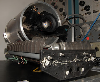
Building a rotating cradle to allow on point unrestricted tilting of my video camera for deployment in video feedback.

This is the build up to this point, camera is mounted within an aluminium drum riding on rollers. I understand the drum is an out of spec helicopter part that I salvaged from a scrap bin, the rollers are from an old color photograph processing machine with One Drop yo-yo parts elevating the drum (and all the non-round elements) clear of interference.

I should have taken a picture of this prior to modification, it'll have to wait until I grab another one (I believe there are three of these: developer, stop & fix) to photograph.

My initial visualization of the mounting of the camera was a lot more elaborate than this, which amounts to a 1/4" 20 tpi screw through a shaped woodblock into the tripod mount of the camera. I've still got to remove some material from the woodblock as it places the camera just a touch high of center.

This was a problem at first. I had initially been designing around the solid roller support depicted in the baseplate picture above. My plan was to countersink the hardware into the sidewall of the drum, but while the drum is indeed quite thick (roughly 1/4") there would not be nearly enough material remaining to carry the weight of the camera.

Furthermore, each solid roller rode on a couple rubber rollers that tilted outward due to limiting myself to precast positions in the plastic end plates (that is to say, the outermost roller is lower than the inner). This resulted in the solid roller wanting to walk off the supports when the drum was rotating toward it.

I installed the shrouds on each side to eliminate the walk off problem, but the solid rollers would still shift, which resulted in the entire assembly moving off center as well running contrary to the entire point of building a centered rotating mount in the first place.

So I had a two tier puzzle that needed resolving: A) I needed a gap that will allow the button head of the hardware to pass the rollers without being a disruptive speed bump, and B) I needed a simple and unrestrictive method to fix the larger bearing rollers in place.

Both puzzles were solved by ousting the heavy solid bar, and wiring up One Drop yo-yos to the structural bar below the rollers.

Plenty of gap to allow that screw head to pass.

I still need to reduce the size of the wooden shim, but it's close enough to center to work as is at a live video show this coming Friday. Extended plan includes motorizing the drum and incorporating CV response to the motor driver.

Tuesday, July 31, 2012

I mentioned previously that the Panasonic WJ 545P special effects generator does not supply the necessary power to run the WV-3250 camera through the 10 pin connector. I had, at the time, shrugged this off as the external power supply works just fine.

What I didn't factor in was the element of sync, which happens to be quite crucial for legible video. As it stands, it would appear as if the WJ 545P cannot lock to a composite video signal at the PL-259 input (my abilities as an operator may be at fault here). At any rate, having the option to power the camera at the SEG is enticing, whether or not this will sort out my sync issues remains to be seen.

I believe I've already taken pictures of drilling metal, so let's just skip to the result. +12 volts at roughly 500 mA is fed at pin 10 (pictured with the blue wire sans heat shrink), referenced at pin 9 (behind the blue wire). Naturally the surrounding pins are to be left alone.

Not a whole lot of room to work here.

Here's the result. Some liquid electrical tape that was used to insulate the ends of the disconnected wires, since I have misplaced my heat shrink. The idea was that the end result would be cleaner than electrical tape which can unfurl over time. I wouldn't call this cleaner, so I'll just comfort myself on the permanence aspect.

A bit of heat & melt due to space constraints, could have been worse.

So there you have it, DC power input for camera channel 1. Since the SEG supports only two channels simultaneously I didn't see the point in modifying more than one input, as I have multiple SEGs that will cascade into one another (forming a loop if I choose) and the power supplies I have earmarked won't support more than a single camera. I'll just allocate channel 1 as a powered input for each.

Sunday, July 29, 2012

Let's take a quick peek at another vintage monster in the to-do pile.

About a month ago I ran an eBay search on Panasonic WJ 545P and got a low starting price hit, I then had a peek at the sellers other listings and saw this.

As it would turn out, no one else saw fit to have a go at anything I bid on that day.

So in my recent fit of video allocation, I have essentially ignored the protests of that part of my brain that deals with the logistics of spatial order and have migrated from a critical mass NO BUY frame of mind to a "Holy shit! Cool stuff!!" free for all buying marathon.

I do believe this (as in, the growing video pile, not just this particular device) will force my hand at culling the herd a little bit.

BNC interface, with a hinge..

Guts!

The rear access guts only go so deep. I'd love a shot of the gear reduced wipe controls, but until I actually start digging into this with repair on my mind I'm going to limit the exploration to easy access.

More guts topside. Circa 1977, this is always what I sort of expected to see when cracking open video gear, but to date the majority of circuitry I've seen has been discrete.

Power up carried both good and bad news. It powered up... Also, running the wipe varied indicator light intensity of each input block in relation to position of handle, indicating proper function of that branch.

However, the preview & program output channel selectors (lit at lower left) were unresponsive, and the program bus appears spread out across four channels. Granted, I'm only going on lamp indicators and not observed signal path.

The wide range of video signal types, available simultaneously (I'll get to that device soon enough) coupled with simple tricks such as this truly make video a fascinating format.

Saturday, July 28, 2012

I have been remiss in updates, and there is oh so much to talk about, but for the moment I'm going to just fast forward over all the other stuff to yesterday.

When a yard sale just up the street sold me this 70 pound, 300 lumen CRT projector hailing from 1987. I present the Kloss VideoBeam 3000! Yes, that is a standard width doorway in the background.

29 Kv according to this fine brochure which is worth looking at for pictures alone.

Input block is impressive, and I am elated at the RGB plus sync block, as this thing (if it works) will see permanent studio installation for video manipulation (it's probably too underpowered and heavy to serve any other purpose).

Input block is built on a mother/daughter board type configuration. Everything large enough that circuitry work isn't some mind numbing prospect.

I only pulled one card, and this is what I saw..

Fixed it! Hahahaha, I had toyed with the idea of firing this thing up once the cobwebs and mouse shit were removed from the innards, but now I feel compelled to pull all boards and spot check obvious failures before doing anything rash.

Plus, the longer it's opened the less pronounced the lingering smell of cat piss will be.

PS: http://www.remove-cat-urine.com/cat-urine-article-directory.html