I purchased a Tektronix 575 in untested condition at an estate sale last Thursday. I had a selection between two complete units and a parts unit (missing CRT), and being allowed to crack the cases and peek inside I selected the unit with the least amount of dust inside.
While this was the cleaner of the two units, it was not without its issues. Visual inspection indicated a failure in the base step generator mode switch, and less than optimal conditions with respect to the capacitors on the -15 volt rail.
With respect to the switch, try as I might to simply reach inside and twist tines with pliers the actual repair required removal, disassembly, introducing a suitable curvature on the tines, and re-assembly/installation. I did not take many pictures of this process, as I was not in a documentation mindset (outside of taking a standard set of assembly orientation pictures some of which we see here). But I'm sure anyone can replicate the process if need be.
Once the switch was operating satisfactorily I decided to ease it onto power and get an idea if I needed to spend another afternoon in the car and try to grab the units I had left behind the day previous due to space and money. Thankfully, there were no burn-outs; but beyond the horizontal trace mildly varying intensity in steps or moving side to side I could get no vertical deflection or movement whatsoever. Also, the CRT was (is) cock-eyed.
Popping the side panel off and taking a look at the inside while running I noted a tube did not have a visible filament glow, nor could I spot its getter flash. Power down, grab the tube - it's hot. Sure enough, it's the 6GU7 in the vertical amplifier section - and the flash has oxidized into the tell tale white reside due to a visible crack through the base of the tube. Spend the next half hour digging through my stash to find a few candidates and show them to my tester. Insert a "fresh" 6GU7 into the vertical amplifier section and away we go.
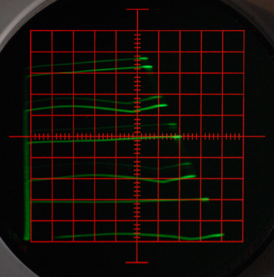
Where did my nice straight lines go? Also looks like I over-corrected on rotating the CRT (which is done while the unit is powered off because the adjustment assembly is currently broken and I don't feel like grabbing the yoke of the CRT while charged).
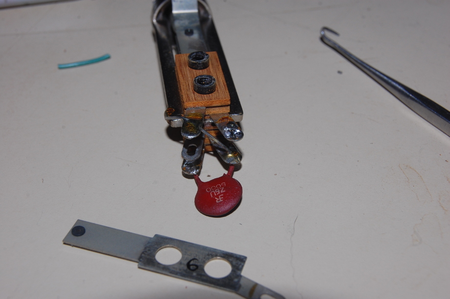
Now seems as good a time as any to replace the visibly leaking capacitors.
Instead of waiting out a parts order I decided to use up some parts I have on hand. The original circuit section had four 2000 uf @ 20V in parallel on the lower negative voltage rail. My little assembly measures a bit more than 8000 uf and is rated at 50V. Of course, the replacement did not improve the geometry of the trace on the CRT.
It turns out the trace could be corrected through calibration controls, and a more in depth calibration will ensue now that I am reasonably sure the Tektronix 575 Transistor Curve Tracer is functional.
It's been a while, I hope everyone is well. I'm looking forward to matching up transistors for differential stages in short order.