Showing posts with label amplifier. Show all posts

Thursday, January 05, 2012

Power amp time.

Up for consideration is a late 1970s Spectro Acoustics 202C amplifier. The internet reports a lineage to Phase Linear amplifiers.

Control set is rather sparse. Liberal use of fuses though, each internal channel PCB contains two more fuses. So. To recap: No power switch or volume control; one power cord, two RCA inputs, one 4 terminal barrier strip speaker output and seven fuses

Lean and to the point. Though, mismatched electrolytics on the positive and negative supply rails don't match up to the gut shot I've seen.

Hardly a huge concern, as it's clear these caps are beyond usable lifespan anyway.

While I fully support reuse, I'd feel better if the old insulation had been cleaned of the cut leads (or even, you know, removing the previous wiring completely during the preparation phase of the work).

The preceding lack of attention to details makes me wonder about this fix, including speculation on what sort of "parasitic" resistance the charred carbon path on the visible side of the PCB reflects.

Smoke signals are spelling out the recommendation to proceed with caution.

The Spectro Acoustics appear to be well regarded amplifiers though, so it may be worth the effort to get right.

Sunday, January 01, 2012

This Stromberg Carlson AR-425 has seen better days.

Another "gutted when I got it" wreck, this was in a small heap of leftovers in the basement of an estate sale.

This amplifier is on the wish I had a pair list.

Is that a copper chassis I see? Picked clean, save the actually hard to find stuff. Ground up rebuild is the only way this thing is going to sing again. I'll have to test the output iron and compare to the similar potted Chicago examples as installed on EICO HF-20 & 22, there may be another way to have a pair..

Could use a little clean up.

Friday, December 16, 2011

It was bound to happen eventually. The sculpted bent metal styling that was more or less standard through the 1950s gave way to the angular bent metal that got a foothold in the 1960s. Those are of course generalizations in terms of time frame. There was slop on each side of that date line.

This clearly dates to the 1960s. The fact that someone painted the front panel exaggerates the ugly institutional aesthetics. Here's the intact lettering of a gutted one:

Still isn't winning any design of the year awards, though to be honest I enjoy the ugly angular stuff from the institutional schools of thought about as much as I enjoy the sculpted and primitive platforms from previous decades. Since this stuff is all by and large older than I am, I'll tip my hat to a little respect.

12AX7 weighing in at lower right, one half supports phase inversion for the push-pull output, the other half supports the "MIKE" input. The 6AU6 in the logical position of phase inverter is the line level input/second gain stage for microphone. Can't overlook the pair of 6V6 on output.

It would appear there have been sticky fingers where rectifier tubes are concerned. The red cover at upper right covers an octal plug for input configuration, pictured is the optional Newcomb input transformer. The installed Newcomb part number SF-30 could be confused (perhaps "substituted" is more applicable) with a bit of bent solid copper wiring, ala Romex.

Nothing incredibly odd here. The mains wiring does not appear to strictly adhere to the schematic (following), and the Foster output iron is hanging tough gut-side.

Another octal output connector (the Stromberg Carlson is, of course, wired differently).

I will always be delighted when I open an amp and have access to the schematic. Manufacturers take note!

In boosting the contrast on this image, I noticed a bunch of darker squiggly lines. Which, as it turned out, were present on all recent shots. See, a week ago I noticed a dark spot that was also spanning all images in the same location - indicative of a speck of dust on the face of the sensor. I tried to blow it out, which delivered a spot of spittle. At this point I had to go into fog & clean, and the soft cloth I selected managed to deposit small fibers everywhere. So, the camera is going to get a proper clean once I find my bulb brush, in the meantime I'll live with the artifacts.

Back to the amp, it would appear as if this has been modified as the plate on one half of the 12AX7 is hanging in open space.

CTS potentiometer dated 28th week of 1966.

Foster power transformer dated 31st week of 1966. The electrolytic can cap is dated 3rd week of 1967, that should probably be updated.

Wednesday, December 14, 2011

And now, an early 1950s Stromberg Carlson AU34, but first the logo.

The earth, draped in sound. I can dig it.

Utilitarian beauty.

Top off so we can see what's under the hood. From lower left moving to far right: 6SJ7, 6SF5, 6N7 (doing phase splitter duties), a pair of 6L6 outputs & a 5U4 rectifier.

I baked this amp a few years back. It had been sitting in a damp basement and I wanted to insure the transformers did not contain moisture prior to my attempt at burn in. I want to say it went into red plate, or oscillation. The fact that I cannot recall pretty much nullifies all my prior attention. Looks like either the temperature was a touch high or there was some sort of residue on the metal.

Pretty rainbow colors.

Seems like another amp that predates twisted pairs. I guess it hails from the era in which low enough gain, or short enough bandwidth, made such steps unnecessary. I'll probably leave this one be, unless it proves problematic, unlike some others. Nothing remarkable here, though I do like the primitive (very DIY friendly) approach to tag board construction.

If this was a class, I would offer up this modified schematic (very thoughtful, thank you previous owner!) and the following picture and request theories as to what and why.

Aw, what the hell..

Saturday, December 10, 2011

Last time I put the King under the knife, let's move on to the Knight.

Faux hide, from what I can tell.

Nice and compact speaker case..

..with an amp on board.

Allied Knight Model 93 SX 350. I think this qualifies as "cute as the dickens".

Single ended 6L6 amplifier, puny output transformer behind Coke Bottle 6L6.

Classic labelling on the AC mains cord, sometimes that specifies the quieter of the two positions, other times it's an effort to keep phasing unified across multiple electrical units (reducing the chance of two chassis being hot in relation to one another). This all becomes moot with a proper 3 prong plug.. which is a baseline standard in my world view if reviving an old amp.

Looks like a late (early December) 1954 Quam driver. The seven pin Amphenol connector seems a bit overkill compared to modern speaker connectors, multiple output taps to match the output with the load was more commonplace in that day. However, the neat element of a speaker being wired up to reflect the correct load when plugged into the amp is shot down when you factor in the fact that the amplifier manufacturers didn't standardize anything, as "universal" means "bad for business". [Deep breaths and good hot coffee, helping to stave off a rant..] So, we essentially wind up with a lot of various set ups here, sluicing our way to separate "matched" systems. If you're say, putting together a collection of goofy old amps and speakers for something like a recording studio, where the widest range of intermingling is preferred, you'll either have to punch a 1/4" (or some other standard simple format) output in there, build and live with a mess of pigtails or decide on a wide hole multipin format and build it in all the amps. So, you'll have to choose your point in the balance between invested work, hassle of operation and original appearance (AKA, condition). I realize that functionality trumps originality in terms of value, currently, but 50 years from now?

Now THIS is a clean interior.

Multi-purpose of unallocated 5Y3 socket pins to select primary taps to reflect mains voltage. I'm excited about the 130 volt tap, that'll go easier on all involved components.

Printed schematic in the bottom of the enclosure. Simpler times.

Union built. Doesn't seem like the unions succeeded in retaining the wide spread production of electronics on a domestic front. Shame that. Though, clearly it wasn't in their control, nor was it really their battle alone. I'm not in the mood to chase that subject (Mmmmm, coffee), as it tends to end up to heavy on the pointing of fingers and too light on the sucking it up. I really added that because I like the illuminated fist. Nothing like a fist logo to really drive your point.

In other news, I'd like to know why hammertone finish isn't more popular on automobiles. I'd love to have this finish on the VW.

Thursday, December 08, 2011

While I'm digging through a bunch of neglected junk, I figure I may as well begin with the older, more attractive designs, then roll out the later uglier beasts until I reach a point where the units at hand do not merit my banging out a few words in their honor; they will then be quietly rendered into parts and no one will be the wiser.

Here's a Manatt-King Radio Company amplifier, with nothing else to go on I'm going to conclude this is a "KING" model and refer to it as such.

Half cage rear enclosure, I believe the selector dial at left is an output impedance selector to match up to whatever is plugged into those 4 pin Amphenol speaker output sockets, the loose trunk wiring of which we'll see in the upcoming gutshot.

It's hard to discern what's what here. Going left to right, I presume we're looking at a rectifier, pair of outputs, phase inverter and a trio of preamp tubes doing preamp and/or mixing duties. Come to think of it, I was just shuffling through a pile of amps without really digging into them, so chassis labeling may be evident underneath that carpet of dust.

More sign of post factory work. The series pair of CC resistors are clearly in a more modern package, and the PVC jacketed wire is also pretty suspect without a time machine. The tagboard circuit and over all layout is pretty clean though, so there's potential. What's this? I do say, we've had a cookout!

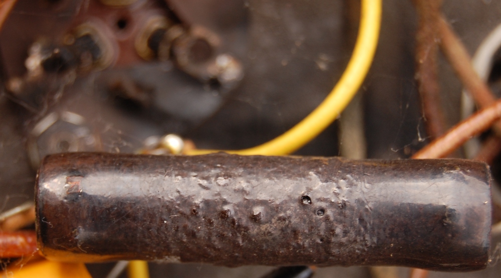
Wirewound B+ dropping resistor, a touch worse for wear..

..beyond which is an indicator this unit has had something of an electrical mishap in the past.

Smoke stains, never a comforting sign. When/if I get around to this one it'll entail spot checking everything down to the iron and more or less rebuilding it all. Pretty nice doorstop though.

Tuesday, December 06, 2011

In case you haven't yet surmised, this is turning into amp month. I'll be busting the shell on a lot of neglected iron in the coming weeks, largely so I can get a current order of magnitude figured in relation to actual depths of the project pit.

This logo speaks class. What the hell happened where it became important to add obnoxious stuff like blue LEDs to garner attention from the buying public? I guess sliding backwards is movement too..

David Bogen H-30. I'd put my chips on the model number containing, in secret code, some indicator of output power range we're looking at here.

Apparently this was in a harvesting pile before I carted it off, which in my mind initially equated to being picked apart far more than it is. A couple wayward octal sockets, and a little this or that - but largely intact. All the iron is there, which is huge (assuming functionality). The upper and lower metalwork is absent, though who knows where they've wandered too. There remains a chance of recovery, and worse case this will offer a decent challenge in metalwork, should I decide to pursue restoration.

Of course, it's easier to understand this unit escaping a more thorough dismantling when we assess the condition of the guts.

Not the first line of selection when it comes to input connector either.

Hmmmm, We've passed beyond plug & play territory here.

Those caution yellow Sprague electrolytics appear to have a date code placing their manufacture in late 1965, they are most definitely the result of work after the original manufacture (which dates to the early 1950s unless I am mistaken).

This exoskeleton could hail from an era in which a civil nuclear mishap was unheard of.

Here's a tired 1 watt carbon comp resistor, ready to offer up its own special mix of thermal, shot & contact noise. This means it will always have a home somewhere..

Does the CDE Black Cub predate the CDE Black Cat? I guess that question is not really germane, what does matter is that this capacitor has no business tying AC mains line to chassis.

The 1950s era plasticizers used in the power cable have evaporated, or otherwise migrated beyond the confines of the insulation on the AC mains wire. Eh, I would want a grounded cord anyway. I wonder what ratio of that nice fluffy cord filler is asbestos. Sorry, hazardous substances have been on my mind of late, just wait.

Depending on condition a bit father in, away from heat sources, this cable may find itself a new purpose as speaker wire.