I recently put together a very non-standard (read as experimental) build. Much of the planning process and circuit level work had been completed by the time I started taking pictures, I only thought to grab the camera once things got interesting.
The build itself contains two duplicate channels joined at the controls of an RMA Tetanus Booster (signal preamplifier) alongside a root Crustacean (three stage noise source, an early prototype of which I touched on a couple/few years back) feeding an output section & transformer.
Aesthetically speaking, I wanted no visible assembly hardware topside. This required fabricating brackets that would secure the wood side cheeks from the inside.

The brackets were marked for alignment and drilled to accommodate jacks and switches which would double as mounting hardware. Working in thinner wall (20 or 22 gauge) mild steel makes it possible to build with a stack of multiple metal elements and not run out of thread.

The cracked glass LED lens is held in place with a spring resting on the LED bracket, straddling the LEDs. The LEDs themselves needed a flat ground on the outermost face (in relation to their triangle) of the light emitting "dome" to allow the half inch nominal diameter spring to rest on the bracket and not teeter on an LED.

Trial run of fitting the sides to see how it sits (corrective twisting at this stage before I loaded up on more hardware proved wise), and a test to make sure I could install the cracked glass from "beneath".

I knew the markings were sized to the knobs as I had a doweled dummy knob while labeling, but I had to lay my eyes on the finished geometry with the glass in situ.

A problem I have fallen into in the past is that of proceeding on the externals before I have a 100% clear idea of how the interior elements are going to sit. This build proved no different.
Initially my thought was to bend some L profile shelf pieces that would secure to the inside of the wood side cheeks, providing a mounting point to tie a metal plate from one "wall" to the other. This would double as another structural tie while it provided a method to mount the number of circuit boards this build required. The mock up pictured was placed with this approach in mind, but visualizing the build methods it would take to pull it together while allowing future access for repair/etc was not working out with the area I had to work with.
The most obvious issue revolved around the output stages (resting on the rear rim), I had originally thought to mount those tucked behind the audio jacks at rear, but the output transformers were an interference fit even before introducing a mounting solution.

The solution for where to put the output section offered itself by way of unused space in the front of the unit, past the switches which had proven themselves too "deep" to allow spanning that area with a circuit board. I bent up a mounting plate that would nest in the nose and secure via the bank of switches. Strips were cut into the metal and folded around the transformers to keep them in place.

Meanwhile the wood cheeks were shown another sanding pass and a coat of tung oil.

The output subassembly tucked right into place, and the load on the switch hardware is minimal as everything is a tight and flush fit. The front proved a better choice for mounting, as that is where the effect bypass and output polarity switches live, so wiring runs are shorter this way than as originally designed.

4PDT bypass switch (true bypass with no LED indicator for two channels) displays plenty of room between itself and the transformer legs.

Since I had freed up the rear space in the enclosure by installing the output stages up front, it only made sense to mount the input sections at the back and buy myself a little needed elbow room for the other three boards. This was facilitated by yet another bracket; this one spanning the audio jack & DC inlet plate and bending down for the mounting point.

Marked in black is an interference fit that occurred because I fit the rear mounting bracket to the outer shell without the side mounting brackets in place. The side brackets are fit to the shell, so I cannot simply swap the mounting bracket into the middle position I have to trim the bent profile down. It was easy enough to avoid kinking my angle with snips.

Contrary to the situation at the rear, the front carrier is tight enough to the outer shell that I opted to guide the front side bracket proud of the PCB mount. I considered trimming them to prevent any overlap, but since the front subassembly is carrying transformers I figured the additional securing was preferable.

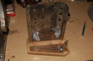
Since I nixed the idea of wall mounting my main PCB mounting plate, I fabricated Z profile mounting legs affixed by the potentiometers. This will allow my mounting all circuitry off the bottom plate, which is a design method I'm striving for in the future.

I cut paper into a shape defined by two Crustacean root PCBs into the shape you see here for proof of fit.

So far so good, and there remained space for the third, LED drive circuit board.

On to wiring the control path. I had, in the infancy of this project, figured I would just flying wire finish the 10K summing resistors that join the post volume control sections of white noise, low pass noise, variable crackle, and audio input. Having developed a better feel of the cramped intensity this build was turning into, I added yet another circuit board with two 4 into 1 resistive mixers mounted to a shorter Z bracket.

The installed circuits were already wired, demanding a flying wire management system.
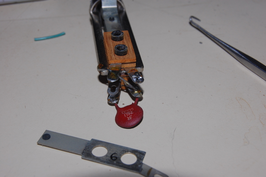
If you look close, you can see that the two inner mounting bolts for the Tetanus Boosters have been shortened. This was due to an un-pictured test fit involving the LED driver board.

If you sight up the grounding lug of the Switchcraft jack you'll observe a resistor lead that looks as if it would potentially offer a short circuit condition if the jack should become loose and spin. The upside is that exposed lead is itself at ground potential.
I had employed the Switchcraft 12A to normal the A channel output to the B channel input when no cable was inserted on B in, but it was a very noisy connection (yes, I realize this thing is generating noise, but there's a difference) so I clipped that wire out. I reason that the operator can still cascade the two sides with a short cable, but at that point the massive influx of noise is no longer a design sanctioned element and so they can either be delighted at the discovery of this behavior or decide it isn't a swell condition as I did.

Wiring begins. Hey, I'm going to need to establish some guide marks to make sure I don't accidentally cross pollinate the channels.

More flying wires.

Less flying wires.

I'm pretty sure this picture marked the end of a day, and I just wanted to see what a complete build was going to look like.

I bolted the paper pattern in to transfer mounting holes.

I'm skeptical that there's enough space in that gap between the trimpot and straight edge to allow the metal plate and mounting hardware, so the "downhill" PCB will be rotated 180 degrees to shift the taller stuff to the rear.

High time to do another fit check on the LED driver board. This is so the LED will change depending on output signal strength, it could be a ridiculously small printed circuit board with SMT, but no, I'll go with socketed DIP on a huge chunk of proto-board instead.
Party animal.

There's plenty or room for the second Crustacean, so let's get this party going.

An artifact of geometric constraints is offsetting a pair of PCBs that defined the size & shape of the plate on which they are mounted.
I know, if this was part of a rocket going into space the baseplate would be define by mounting points instead of edge cuts, but I'm a simple man.

Something about this point really drove home the light at the end of the tunnel aspect for me.

I like my tolerances tight.

STUFF IT! STUFF IT! GO GO GO
It's risky, these stretches that one clings to as being a final pass. I know this. I've dug myself into plenty of holes, but I'm usually able to dig myself back out...

Final placement mock-up is looking okay.
At this point, with this particular build, I'm hazarding into race mode, because everything is over due. I could weave a long tale as to why this is the case, but in the end things we've heard a thousand times before are boring retreads not worth mention. Suffices to say I am motivated to complete as soon as possible.
Meanwhile there is a niggling sense that I have overextended myself and am operating in a state of unhinged overconfidence.

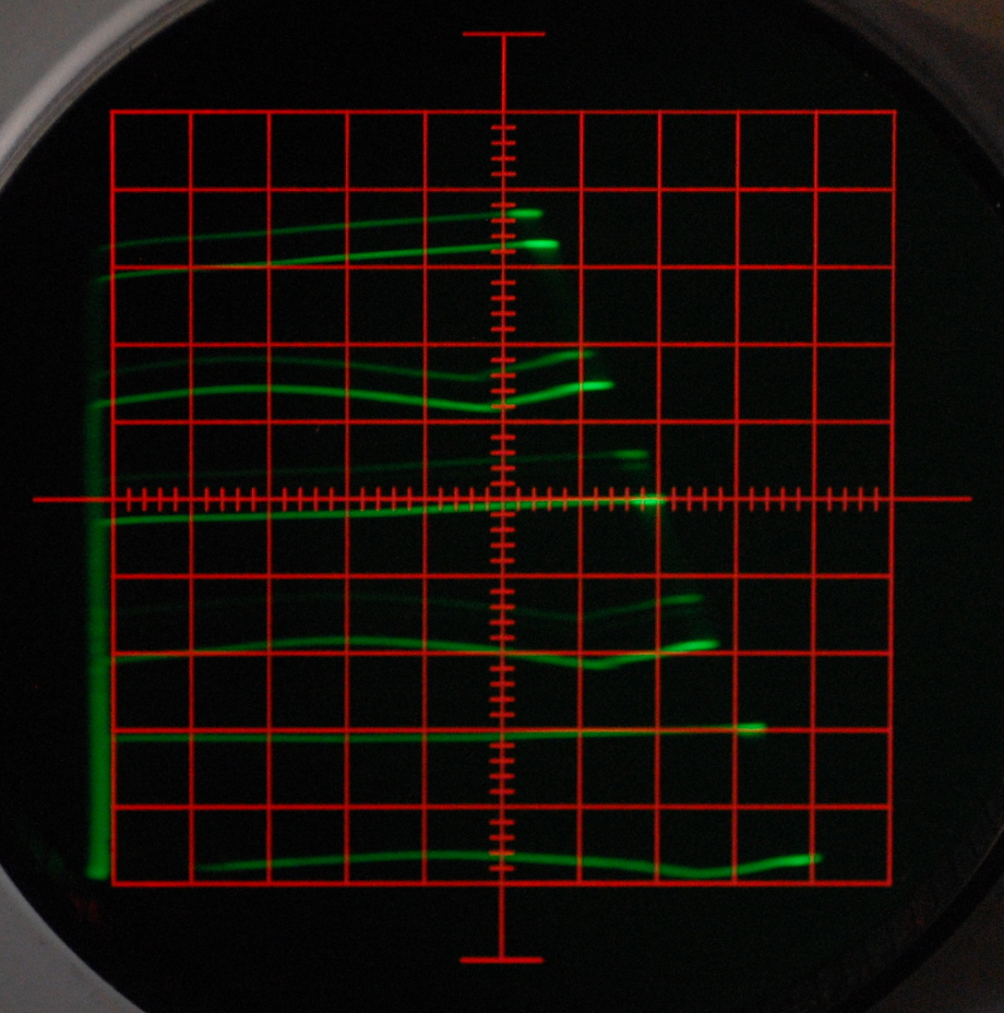
LED board is not wired up and accounts for all the flying leads topside. I have not wired up the output section to polarity switch, because I want to look at a trace on the scope to prove I adhere to the labeling scenario I have already established on the faceplate.
Aside from that, everything is wired up and ready for test.
You read that correctly.

The gain control had been wired backwards. An annoying fix, but not terrible.

Confirmation of circuit operation paved way to wiring up the LED system...

...which overhangs the baseplate closure plane by a healthy degree. I doubled the nuts on which the Crustacean boards rest to clear the metal plate mounting screws, and as a result pushed everything outward by the width of a nut. I resolved this by folding a hem on the (insulated) baseplate which results in a little more interior headroom.

Out the door the same day it was finished, but it was a fun while it lasted.