Monday, January 31, 2011

Time to modify the Century 8710SC. This process turned out to be far less of a chore than it could have been, because of the cheap design.


Here's the disassembled OE rectifier. AC enters the PCB at left which was riveted to the aluminum plate that doubles as heat sink and positive voltage rail (the slot at the upper mid point in the picture bolts to a thermal switch which delivers to the positive feed). The small wheel-like objects are the diodes, they were literally compression fit between the PCB and the four divots in the aluminum. One of the diodes is shorted.


The divots happen to be aligned with the fixed spade connectors at the secondary winding of the transformer, and two of them were drilled out to accept the DO-5 diodes shown. The diodes are 40HR10, rated at 40 amps.


My alignment isn't spot on, but all the materials involved have a bit of give so I'll make this work. In retrospect I probably could have built this with the diodes fed through the other side, but still feel that would put the lug a bit close to the case.


With minimal fuss this went together.
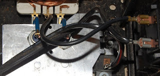

I wasn't incredibly concerned with diode polarity, if the anode/cathode of the new parts was reversed from the old I had the option of simply reversing my battery leads here. To my relief, the electrical orientation of the parts was correct right out of the gate.

After reassembly I took my untested, ailing battery and hooked it up. Current jumped to the top of the scale (so much for 2 amps) and the heatsink began to warm up, enough so that if left for a span of minutes it seemed conceivable that the heatsink could melt the insulation of the AC feed wires I had bent around it.

I required a trickle setting. This fix (unpictured, sorry) was achieved with an ON ON SPDT switch on the negative leg between the center tap of the transformer and the current meter. One position completes the circuit through a wire for normal operation, the other places a 150 ohm ten watt wirewound in line with the negative leg, reducing current into a dead short to less than one amp.

The truck battery remains in the realm of the non-existent, but I feel far more comfortable operating my charger from here on out.

Sunday, January 30, 2011

Made another metal run yesterday, now I have the fundamental material for the gantry on hand.


Here's a cross section shot of the X axis gantry beam, it's a touch more involved than the SketchUp drawing I drafted in October. One point of concern I have here with the current loose mock-up is the linear bearing rail situated over the blue faced material will require a countersink channel on the inner angled face of the C channel wall to accept mounting hardware (unless I opt for threading the holes in the C channel, which is a design tactic I'm avoiding at the moment).


My main objective is to confirm the clearances I came up with on paper. The dimension of that nut pushed me into an adaptive frame of mind.


The bearings / Z axis car has a clearance of 0.2865 on paper, which adheres to my desire to keep roughly 0.25 clearance between moving parts. However the nut, suspended inside the channel as pictured, has 0.0335 inches of clearance. Initially my thought was to modify the nut to reduce the chance of interference, but there's also the matter of the bracket that ties the nut to the Z axis car. Not to mention that the nut itself is a point of wear, and will eventually need replacement.


I want to keep the spatial displacement of the axis' as small as possible, as off axis distance equates to magnification of slop. My current plan is to "elevate" the screw in the channel to position the nut so the collar rests on the inside face of the Z car, essentially putting 0.3730 of the mounting flange into the baseplate of the Z car. Since placing the flange on the outside edge of the car will reduce usable travel by roughly 0.3785 (widening the car), I plan to cut a slot in the baseplate of the car to accept the nut. This will remove one screw, the remaining three will tie into an L bracket milled into a horseshoe shape on one side.


By repositioning the screw the motor mount hardware will clear the 3 inch C channel, which will come in very handy should I need to R&R the NEMA23 motor. Not pictured here is the 0.5" thick "wall" that will cap off the X axis channels, provide the plane to mount the motor & bearing at far end of screw and tie into the legs that are not pictured, but are rendered in the drawing below.


So, visualize a 6x14" plate of 0.5" thick aluminum bracketing the ends (and obstructing the view of the cross section) and you've got it. I may have to remove some material from the car side of the upper branch of the 8 inch leg channel, but that will wait until I've got the gantry assembled and am mocking up the car.

Saturday, January 29, 2011

Lately I've been considering the inclusion of pending automotive exploits on these pages, technically speaking an automobile is more of a machine than an oscillator. Of course, some of the prohibitive elements is that working on a car is a messy business that's been covered in great detail elsewhere. I probably will pollute this place with some chatter about the type 3s, but I'll endeavor to keep it appropriate.

Nudging closer to this eventuality, I'm up against some sort of electrical goblin in the truck that drains the battery. Attending to the flat battery ushered in the realization that my Century 8710SC battery charger (known in the vernacular as a cheap piece of shit) is hosed.

To illustrate how much of a cheap piece of shit this is, let's disassemble it to have a look at the guts.


Right out of the gate, an indicator of quality. There is no hardware used in assembly outside of the occasional rivet securing interior components. Bent metal construction has one method of disassembly, it involves bending metal (again) which is obviously not a path to longevity.


My first approach was direct, utilizing the screw driver oriented as pictured I attempted to pry the tab out. Sadly, due to constraints established by tool depth and hole size I couldn't exert more upward force than face loading and the tab simply popped into the position shown.


Next angle proved effective, and limited unnecessary disfigurement of the metal to the tab itself (which could technically be bent back into shape should I lose my mind and decide to employ the same method of assembly the original designers opted for).


Naturally, the tabs (yes, plural) that had been pushed in farther than original were considerably less pristine when finished. I had to alternate sides and disfigure the tab prior to establishing clearance enough to pry it out. The enclosure is, however, in much better shape than it would be had I employed a BFH to expedite disassembly, which was plan B.


I may have found the problem.

Primary wiring to the right ties hot AC mains to the transformer, and switches neutral to various legs in order to determine operating voltage and "output current range", which, must be tied to the thermal switch to interrupt the cycle once the transformer begins to overheat.

From the top:
Blue: 6V @ 10 amps
White: 12v @ 2 amps (my preferred setting)
Black: mains hot
Black: 12V @ 10 amps
Yellow: 12V @ 55 amps for starting

I don't think I would use this to start a car on a bet. Especially since this particular unit shows a shorted diode on the rectifier at one side of the center tapped secondary. Leading me to believe that there may have been an AC component to the battery feed side of the leads.


Here's the offending part. I'm considering replacing this with a high current diode pair, fixing the range switch so only one range is available and the other ranges are "off". In the meantime it looks like I should go get this battery checked to make sure it wasn't destroyed by my failing charger.

Thursday, January 27, 2011

It took me a week to execute a simple task. Referring back to the interference fit for the Z axis screw, my planned fix involved cleaning the threads on both parts and filing down the folded thread on the screw.


My initial mock up here, in which I've placed a knife in the channel between threads to act as a protective barrier between my filing work and good threads, proved cumbersome. In the end I simply held the file as I would a pencil and exerted more care than slop.


Success! Sometimes the fastest fixes are the most satisfying.

Next phase of the CNC project entails getting metal milled for the gantry. Once the gantry is solidly defined I'll build the frame on which it connects to the table, most likely out of wood since my budget is wearing thin. I reason that the framework is a bolt in layer, that can be upgraded if wood proves inconsistent in dimension.

It also looks like my initially just hoped for feature of a spindle RPM control for the Porter Cable 75192 fixed speed 3 1/4 HP router motor is achievable with the Super-PID closed loop controller. I think I would have easily burned up more than twice the cost of that trying to engineer something myself.

Tuesday, January 25, 2011

I'm not really one to get rid of stuff. A friend spied this in a clutter photo and voiced interest in it, so it's only fair that I go through it and assess the potential and value within.


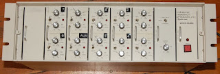
The Industrial Research Products, Inc. Voicematic DE-4013A-0100; what amounts to a conferencing 10 into 1 microphone mixer that can duck inactive microphones. This unit contains one DE201 master level module, five DE202 dual microphone channel modules, a blank and one DE205 regulated power supply.


The DE201 contains an LM339 voltage comparator (presumably for the Voicematic level ducking circuit), a Harris HA3-4741-5 quad opamp and a variety of metal package transistors.


In addition to various discrete actives and Beyer TR/BV370 215 006 microphone step up transformers, the DE202 contains an MC14528B dual monostable multivibrator (presumably the respondent to a CV level message provided at the master LM339), a TL083 and one half of an HA3-4741-5 per channel. Component quality here looks pretty upper shelf. The only real questions I have is if the mic pres have usable gain and how they sound, the AGC circuit can be bypassed via front panel switch, so ducking artifacts are not a concern and could prove useful in certain circumstances.


Lead dress is often an indicator in regards to over-all attention to detail, which can factor into sound quality. I remain curious as to how this unit sounds, I'll have to cobble together a rough approximation of a studio session to check this thing out.


Looks like the analog circuitry is going to be seeing +/- 12 volts.


The orange/white twisted pairs are microphone feeds to the channel inputs. I believe all the channels are dumped onto a pair of these wires as a low impedance signal amplified by the HA3-4741-5 at the final level stage.

The aspect of this device that had thus far impeded my interest is the ten in, one out architecture, which isn't something I have a lot of use for. However, in speculation I realized I can switch in a bypass routing that will pull a card pair off the main output and route output to a jack on the rear of the case. The five switches can inhabit the face of the blank panel.

Examining the card also revealed a couple wire jumpers in prime positioning for a phase reversal switch, adding to usability of the preamps. Assuming of course this thing sounds good enough to justify the tinkering and 3U of rack space, which remains to be seen.

Saturday, January 22, 2011

I hope you like yellow.


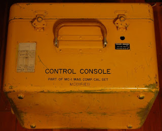
Huge round of thanks to BLOODSON DRIFTER for dropping this CONTROL CONSOLE case on me. This this is full of its original parts and a bunch of circuit boards from an Elka organ that I'll cover some other day.


Part of MC-1 MAG. COMP. CAL. SET, "modified", which at this point is absolutely accurate. Built by Sperry Rand to Mil Spec C-26524, which I think has to do with the ruggedization of the case. This appears to have been surveyor equipment.


Gutted is a form of modification. The panel as pictured is downside up from original positioning, evidently the original purpose was facilitated by having the lid swing out toward the operator. My thinking is that this case is appropriate for a synthesizer build, but only with the panel positioned as seen. That's for another day though (eh, it'll take a bit longer than that), time to dig through the contents and see what's here.


Most of the stacked switches bear the manufacturing mark of "CINEMA PLANT/HI-Q DIV", a date code sitting somewhere in the latter half of 1965 and a part number. From left to right the part numbers are: 65054, 65062, 65059, 65061, 65060 & 65060.


This frame illustrates the construction of the switch/attenuator with a little more clarity.


Part numbers: (ASSY) 2587148, (ASSY) 2587148, (ASSY) 2587201 & (ASSY) 2587201. The two assemblies on the left carry transformers, the two on the right are mainly comprised of a "MOTOR GENERATOR" coupled to a multi-turn pot through a series of gears that substantially step down motor RPM. The motor appears to be set up for 33 volts at 400 hz AC, 28oz inch at 9500 RPM; the generator providing 26 volts. It'll take a pretty low Z signal for the 2500 ohm potentiometer to deliver acceptable results as a VCA (A standing for Attenuator). Perhaps VCP would be a better term?


Part numbers: (ASSY) 2587953 & 65063 (the part pictured above in the close up). Assembly on the left delivers the visual indicators of Degrees & Minutes and carries a multipin connector for interfacing to other equipment. That assembly occupied the large rectangular hole in the panel, for which I have other ideas.


Part numbers: (ASSY) 2587200, (ASSY) 2587200, 65059 & K650937 (Branded "TECHLAB"). It would seem reasonable that there would be active electronics in this thing at one point or another. A few GE transistors collared into place (preventing positive ID), some decent caps and what appear to be more transformers.

Current thinking in respect to this enclosure and panel is building some fundamental tube synthesizer circuits onto the panel (probably a mix of classic circuits and some Barbour circuits as found at CGS), and utilizing the generous space on the interior of the case for a solid power supply that will support numerous outboard modules as well. Just brainstorming at this point in time.

Thursday, January 20, 2011

Have run into a bit of a back and forth in terms of getting my transport sorted.


These parts are so close as to not actually work as designed. This brass nut was sent as a replacement for a mis-picked Delrin plastic nut (originally shipped in the larger size of the other screws). I'd like to employ the clearly higher quality metal part, but need to make them work together.


My hopes are that the out of whack thread starting at the point it is turned down are what is prohibiting me from threading the nut. I'll file those bent ridges down without side loading and hope that allows freedom of movement.


It's either that or tapping out the nut.

Tuesday, January 18, 2011

Received my ON-Semi MJ21195/96 power transistors for the Soundcraftsmen power amplifier late last week and slapped them in over the weekend. In a wholly unscientific manner I opted on the MJ21195/96 because the response curves tapered in a gradual manner and the ramp up to roughly the 50% current output appeared peppier. Plus they were cheaper, by 57 cents each. If the amp sounds like shit when I'm done, exploring the other output devices is within my capabilities.

That would, naturally, only happen after a recap and some other tweaking the good people at audiokarma.org have spoken of.


This, and a pair of pliers to grab and twist the shaft, is how I reached the rear screws without tearing this thing completely down.


As I wrote a while back, the rebranded TO-3 transistors were less than informative in regards to determining which of the 2SB554/2SD424 pair carried which cryptic alpha-numeric stamp. Direct measurement to determine the orientation of "diodes" on surviving devices was the simplest route to identification, here we see the unobtanium "5A" PNP (2SB554) being replaced with current production devices.

Replacement surgery went well, next up looks to be replacing the differential pair to shed some DC offset on the outputs, but before I go that far I aim to secure a copy of the service literature on this amp to assist in avoiding any pitfalls. Why yes, I probably should have had that from the beginning.

Sunday, January 16, 2011

I washed the upper PCB of the ART DR-X effects unit today. This process consisted of the following tools:


One used toothbrush (largely defunkified through prior use with isopropyl alcohol), one 8x10 photo developing tray, one gallon of distilled water (of which approximately one pint was used here), an air compressor and a heat gun.

I pulled the following shot from the previous write-up:


Since chemistry isn't my strong point, I can only guess that the white chemical growth at the legs of the pins is caustic potash. Therefore, I reason that a mild detergent is probably not required, since the caustic nature of the build up is going to provide more "cleaning" power than I probably need to begin with.


I poured enough distilled water to just cover the top of the ICs, and before agitation a considerable amount of the white build up dissolved. After 30-40 seconds with the brush, I hit the PCB with compressed air to disperse most of the water, then followed up with the heat gun. In order to avoid overheating the PCB, I held it by hand while distributing heat (which was a huge motivator to keep that gun moving). The idea behind the heat gun is to encourage evaporation of moisture remaining after the compressed air.

Something had been bothering me about the source of the saponification; in the past when I've seen this build up it has been localized (or at least centered around) a decomposing battery or electrolytic capacitor. This was distributed more or less evenly across the entire PCB, moreover the back-up battery and capacitors did not exhibit any of the build up.


An aspect of metallurgy is that dissimilar materials will often facilitate corrosion at contact points. In comparing before and after wash pictures, I can't help but notice that a good portion of the build up is centered on joints that were not completely filled in the soldering process.


A closer inspection of the lower, largely digital board reinforces the theory that the poor infill is, if not the root source of the failure, at least largely contributing to the problem. By the mid to late 1990s I recall that ART effects from the earlier part of the decade had gained a reputation of unreliability, which leads me to wonder if the chemical build-up around the legs, which certainly may have been allowing functionally disruptive crosstalk, wasn't isolated to this unit alone.

Perhaps I'll trip over some similar era non-functional ART units upon which to test this theory.

I'll need to grab a larger tray to wash that board though, so this process remains in a state of limbo.

Wednesday, January 12, 2011

I keep thinking back to a television episode I watched as a kid in which a group of colonists stranded on another planet were forced to repair and reuse everything in order to survive. When the relief ship arrived to haul everyone back to earth the primary mister fixit urged everyone to stay behind, as his importance within the community would essentially evaporate once repairs were no longer crucial to survival. He elected to stay behind and everyone else boarded the return ship; it was not until they were riding atop the trailing flame of their rockets that he changed his mind, too late.


We've gone from largely hand built constructions that demand great skill to achieve precision to hand assembled constructions built from premanufactured components to altogether premanufactured constructions. Unrepairable in the climate of replacement, each generation relaxing the criteria of skill needed to maintain operation.


Having largely abandoned constructions built by hand, our remaining frontiers are burdened with the inclusion of heavy industry. Furthermore, disposable culture has tied industry up with the regurgitation of every day objects that could be scratch built or at the very least repaired and maintained from existing stockpiles. A purist will point out that these objects (such as audio amplifiers, engines, computing and communications machines) could be eliminated completely, without negating survival, personal strength or evolution. This, however, places demands upon the masses to shoulder a burden that has thus far been alleviated through the seeming perpetual output of industry.


Of course, it was pointed out some time ago that for every action there is an equal and opposite reaction. Unless something is cyclical and self contained, perpetuation is highly improbable. Which brings me to the root motivation I have for my fascination of repair and with archaic technology in general.


Early technology is built upon human endeavor, it is attainable with simple tools. You and I can build this. Easily understood, should we work at understanding it. The fixation with application often overlooks fundamental construction. The construction that civilization has implemented to shore up its ever reaching (though largely directionless) plateau has become many generations removed from human creation. Hopefully if we awake one day to find ourselves on a depleted plain with limited tools and resources, we'll retain enough know how to forge survival.

Monday, January 10, 2011

It's high time to grok the guts of this old tube television camera.


I believe this is a Sylvania VRF 400, unfortunately any and all exterior labels were long gone by the time I pulled this out of a junk heap (or, if you prefer a little more accuracy, off the shelf at a local reuse/recycling center). I have yet to swab the filth off of the components; and as such am having a hard time zoning in on a familiar date code format, but I think this thing was built in the early 1960s.


I'm fascinated with the notion of actually putting this thing to work, relishing in all the black and white Vidicon artifacts. For my application, precision is far from required.


Underside of the unit is largely dust free, showing off the printed circuit board. To the immediate left is the power supply mounted to a panel that conveniently swings out for access. I love these reminders of technology built with repair in mind, it's a shame that's little more than an echo of a bygone age at this point.


Honestly, I think this unit will require a ground up rebuild to achieve operational status, though I may get adventurous and try it out once the ruptured parts are replaced.


Rather, once I replace the ruptured (and intact) electrolytic capacitors AND update the selinium stacks I may experiment with operation.


Of course, that puts a lot of faith in this wiring.

This camera remains at a lower tier of my priority list. Though I must admit, having contemplated the guts a little it does appear far simpler than I had originally feared.