Showing posts with label oscillator. Show all posts

Sunday, February 12, 2012

I did visit the machine shop on Friday to drop off material and discuss the CNC project, however timing was such that during the one slice of time I've been able to get out of work scheduling was not conducive to actual milling. I only bring this up since, while I was there I absentmindedly left my camera behind.. as most of the weekend has been spent so far in horde mitigation this is no great loss. Seeing as how it was photographed earlier this month, we'll have a quick look at the EICO 488 electronic switch Dan (my magnanimous uncle) picked up in is travels.

A very clean representative. This unit appears to have come from the same place as the 950...

..which appears to have been a much nicer place to live than my first 488, seen here posing with a can of beer for scale. Essentially, the electronic switch was a budget driven solution to a dual trace oscilloscope. At the output on lower right alternates signal from the two inputs at left, the center "Positioning" control defines a baseline DC offset between the two input channels, so when viewed on an o-scope the two signals could be be distinctly separated on the Y axis. The two rightmost controls define range and speed of switching.

The 5852 seen here (as found) is sitting in for a 6X5 (as published per schematic). The 5852 has a higher filament draw, which concerns me as I have experienced power transformer failure in the EICO HF-81 (which was notoriously under designed) and this has established a tip-toe level of respect for EICO power transformers (that should read "power transformers in general").

All blue wire. I'm guessing this is a kit build. Take note of the long, silver .22 μf cap that is straddling the guts...

That cap is an add (as found), and while this unit is the third 488 I've had the pleasure of meeting, it is the first that already had that cap in place. Observe the schematic above care of BAMA. At upper right is the oscillator section that drives one channel into conduction while clamping the other (bias modulation driven by the second 12AU7 tied to the cathode/suppressor of the following 6AU6s), C1-6 define the ranges. In my "modified" unit I've replaced C1, 2, & 3 with values that do not match the counterparts of C4, 5, & 6 providing a lope to the signal, but I digress.. According to the schematic, illustrated at upper right, the plates of both 6AU6 are unified at B+ and tied directly to the signal leg of the 488 output.

This equates to 270 volts DC at the positive output leg in a stock & unmodified unit!

The blocking cap is crucial here, and I was delighted to see it in place. The EICO 488 is a fine example of why I observe and measure old equipment prior to deployment into the studio. The unit itself can output some semblance of a square wave with the positioning control adjusted to offset DC baseline between the channels, but the fun occurs while feeding it audio as well.

There remains switching noise which I have an idea on but have yet to implement.

Sunday, December 19, 2010

I think we're overdue for some gratuitous gut shot.


For this, we'll dig into a mid 1960s Cordovox accordian tone generator, essentially organ guts in a gig-able package.


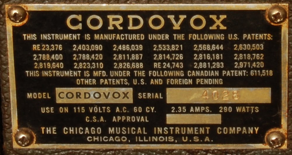
In my preliminary searches I've narrowed the model down to a Cordovox CG, though I see no reference to a specific model on the number plate.


The complete system was composed of the tone generator bank (above); the power supply & amplifier, encased in a similar box with a 2x12 speaker baffle as opposed to the louver behind the grill cloth; and an accordion controller attached with a robust cable and multi-pin connector.


So it stands within reason that a switching bank feeding a couple DB-50 male connectors could put this thing to work. Sadly, I've no accordion controller handy to emulate.


Of course, use hinges on the functionality of the circuit. The deceptively simple control panel sits atop a convoluted wall of circuitry.


A bunch of 6X8 and 6FH8 in the oscillator stacks.


Oh yeah, much better. I believe those two lamps are there to keep interior temps warm enough to prevent condensation.


Oscillators look to be relaxation oscillators built around early integrated RC network packages and neon lamps. I'm betting this unit looks very cool in use (well, if you have X-Ray vision to see through that damn baffle).


Loads of prepackaged circuit components in use here, this thing would be a nightmare to do major replacement surgery on. A discrete point to point rendering of this circuit would be a sight to behold.


Since I'm more or less completely in the dark as to the feature set of this generator, I can only wager a few thoughts to the purpose of this hub or the leaf relay (which actually has 13 tines, the leftmost one being discolored or burnt), my main guess being that these parts support chords.

I had the bright idea of trying to bring this unit up on the variac yesterday, only to realize after the cracking the case that I needed the power amp section (which was left in storage) to supply power to this stage. This particular set came from the bad amp room haul, this was one of the more exciting elements of that haul, as I've had another pair of the same for a long while that had the tubes plucked from the oscillator banks making the possibility of tinkering slim.

Still, this one sits low enough on the priority scale to qualify as a casual project to be chipped away at with an air of nonchalance.

Sunday, December 12, 2010

Let's dig into this Sruthi Madhavi drone box.


...or, if you rather, the Sruti Madhavi.


I guess I can no longer honestly say I live beyond the touch of auto tune.


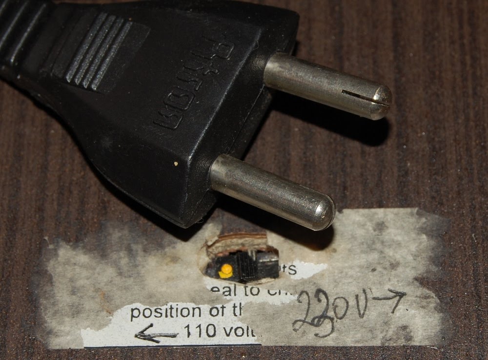
My main idea here is to replace the power cable with something that will fit local wall outlets. Also considering replacing the voltage selector switch with a rocker that, when engaged on the 220v leg of the power transformer will feed all inboard electronics with ~50% voltage. Instant starve switch, since I live in the land of 120 volts.


Gutshot indicates a few things:
A) Output is by speaker only. I'll keep the speaker, but will install a switch to select a transformer coupled output as well.
B) There's no fuse on the AC input, yet.
C) The largely wooden construction offers little in the way of RF shielding, not a concern at the moment, I'll address this only if it becomes a problem.
D) I have some room to work in what will soon be a decommissioned battery compartment.


DIY builders take note! Mounting for the printed circuit board is a thing of beauty, the arms slide into these slots and when the case is closed hold everything securely. Simple and elegant. When the top is removed everything can simply slide out to the point at which the front panel wiring goes taut, which is far enough that board level repairs could take place if needed.


Presuming of course that we could identify a malfunctioning part through in circuit testing alone. I seem to have misplaced my product data for the 8 pin variant of "11". All ICs are similarly scuffed of identifying markings, though I can make out a couple 5s on this chip. Wouldn't find it surprising at all if this turns out to be a 555 based oscillator.

Monday, November 01, 2010

I'm playing a set tonight, and for various reasons I don't want to drag out my full set-up, forcing my hand at a little improvisation. This has me surveying the piles in terms of what relatively compact devices will either produce or pass sound, the forefront contender being a Tektronix 106 square wave generator.


I've determined that the GenRad/Tektronix connectors will take a banana just fine, and since I have a chassis mount banana lug I can ground reference the signal output without resorting to stupidity. I'll consider bastardizing this unit with UHF connectors since they occupy the same sort of space and I can probably pull it off cleanly, otherwise I'll just leave them be. This of course is an eventual plan, and bears no relation to what I hope to do today.


Cracking the case to give it a visual reveals a quartet of 7189 tubes living in harmony with a variety of discrete transistors. Two days in a row now I've peeked at the guts of a tube/transistor hybrid, this one won't be getting the knife though, so I'll have to proceed with caution. Thankfully the transistors are socketed, so in the event that B+ has intermingled with the low voltage buss, part replacement will be a breeze.


Of course, it would appear as if I'm getting ahead of myself, since I'm not going to tackle this level of failure a few hours before a show. Evidently those General Electric electrolytics from 1968 have not fared well over the years. Here's a shot that captures the clear corrode through of the negative lead on that cap, and that murky brown glut is an erupting carbon comp resistor.


Once I find a bit of Tektronix silver solder I'll have a go at replacing this section, and all similar electrolytics. For the time being, I'll have to see if I can burn in my SKL 302 variable filter instead.


EDIT: at 80.9 volts AC mains input, the signal leg of output #2 was sitting at roughly +10 volts DC. Meaning we'll be seeing some more in depth gutshot of this unit as well (also meaning no one will be hearing any signal pass through this beast for a while yet). Here's an appetizer:

Tuesday, October 19, 2010

Barring actually getting anything done, let's have a look at the pile and see what relics are situated toward the top. Of course, current placement in the upper strata means nothing in the big scheme of things. Once I do something stupid like lose a tool the orientation of stuff tends to be disrupted.

PACO E-200-C


I've been meaning to dive into an RF test generator for a while now, and it looks like the Precision Apparatus CO E-200-C is going to be my test bed. The goal, of course, is to squeak out something usable in the framework of audio while avoiding extensive modification. Of course, before I begin down that path, the unit must be gone through. Note the omission of a power switch..

..and, once this "fused" plug is severed and forever dropped into the odd parts bin, the omission of a fuse. I'm also not brimming with excitement regarding the circuit they've built to clean the hash out of the AC mains:
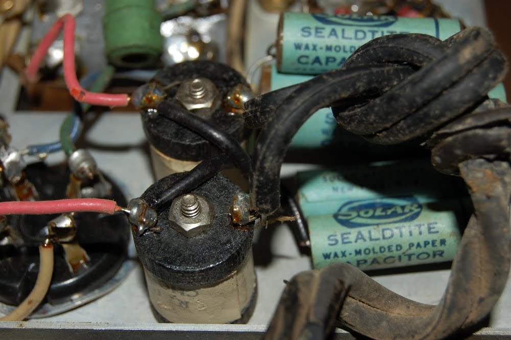
Why yes, those SEALDTITE caps DO tie to chassis ground.

Though I am gratified that this capacitor isn't sweating nitroglycerine, I'll wager what it is sweating is less than swell.
Obviously ready for retirement. I trust the rabid preservationists out there will forgive me my inability to source* replacement paper caps with cloth covered wire, I'll probably reuse that clamp though. (* or having sourced, the inability to justify the cloth wire premium) It would be cool though to drop another stick of dynamite into it, but since the enclosure is without peep slots I'll be happy with some new production shiny capacitor instead.

The OSC circuit itself is a thing of beauty, somewhat self contained on the rotary range selection bank. It's pretty much this section that convinced me to leave the fundamental circuit intact and attempt to implement the device at the frequencies it was built for. Simply put, I really don't want to hack any parts into this section, seeing as how it's a fine example of the quality of build that was more or less commonplace prior to the methodical erosion of quality ushered in by greed during the waning years of the 20th Century.