Wednesday, April 25, 2012

YBA 3 Custom Special Update

...or, it's not always what you suppose it is.

Armed with another variac I resumed an easy ramp up of voltage to insure everything was copasetic and wouldn't you know it, about 50 volts in I hear the "pung" of inrush current draw. Explicative deleted. So, it's NOT the test gear (except, of course, for the one with the faulty outlet). Troubleshooting ensues.

Amp was tubed with dummy load and the stand-by switch was set to play.

1st step: Remove tubes & repeat procedure... "pung"

Explicative deleted. After checking over my work and running continuity tests across the circuit to ground (both of which passed) my thoughts drift to the power transformer.

2nd step: Fire it up in stand-by to see if it's a shorted primary. Acts fine. What changed?

Hmmmm. Continuity check on switch reveals that while the pilot light side switches as intended, the center tap to ground portion (switch is pictured in the stand-by position, nearer half under scrutiny) exhibited high resistance when it should have been a dead short. Several actuations confirm the switch is garbage and needs to be replaced.

So, I theorize that the "pung" at the variac was instigated by arcing across the switch feeding inrush to the capacitor bank of the B+, and it probably wouldn't have been noticed if I cut the amp loose on full mains voltage instead of pussyfooting around. This also provides a satisfactory reason why all my voltages were wonky at the sub 50 volt position of the variac.

I did ponder the option of simply cleaning the switch contacts, since I have access to them.. but somehow every time I think along those lines I am hounded by the image of villagers with pitchforks and torches. Best to swap the part out entirely.

Sunday, April 22, 2012

Yesterday saw a little progress on the modification of the Traynor YBA3 Custom Special

The amp had been red-plating. As it turns out, this 150K dropping resistor (the bias supply is fed from the full high voltage B+ secondary, knocked down and separately rectified) had drifted up to 234K, and the 15K between cathodes of the bias smoothing capacitors had been replaced with a 45K flame proof, effectively tamping the available bias voltage down to useless levels. Hence, a bit too much current flow through the tubes.

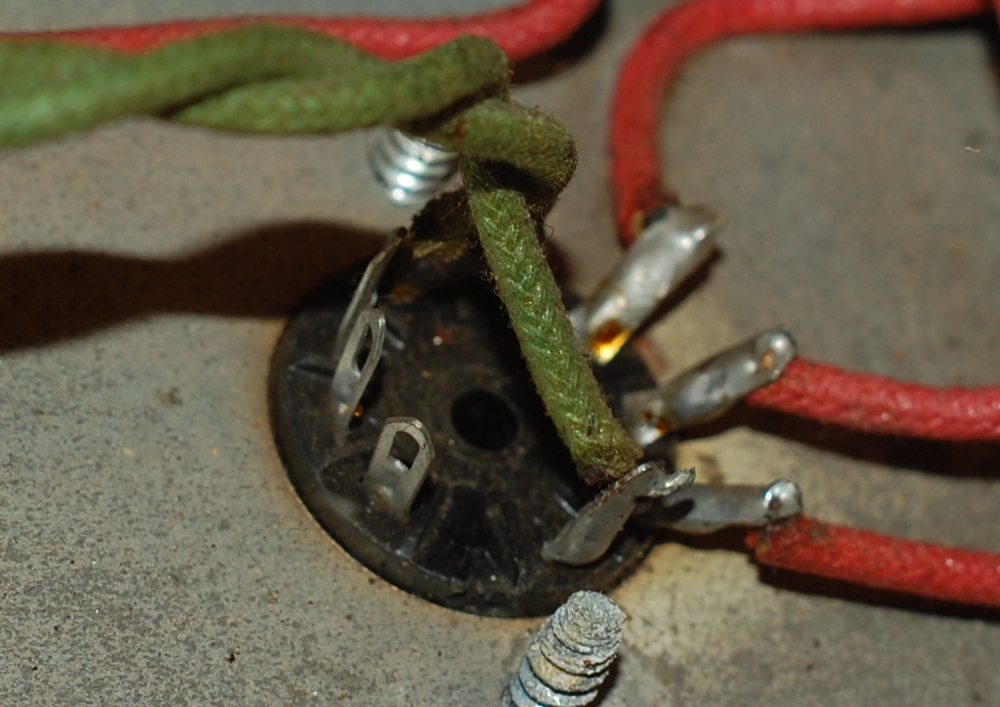
Since this amp is purposed to be a player, and is already far from pristine, I'm comfortable with performing non-reversible modifications on it. To facilitate an adjustable per tube bias tap I undid the original bias feed at output tube grids (the connection above the nut) and removed the two 220K resistors. Full bias is now delivered from the adjustment pot to pin 1 of output tube and a 270K half watt carbon film resistor connects pin 1 (G3) to pin 5 (G1).

I also plucked the 1K5 grid resistors flanking the yellow 0.1 @ 600 coupling caps. As you may remember, I had questioned the lop sided approach to the inner and outer pairs of output tubes. I figure this is as good a place as any to test the effects of resistor distortion, so I planted 1/4 watt 1K6 carbon comps on every output tube signal grid. I realize there's negligible DC drop at this point, but I had the resistors on hand, so...

In order to minimize the flying parts construction, this modification entailed physically switching the alignment of signal path at the post phase inverter coupling caps seen here. Since I had already gutted everything on the "upper" row, switch over was easy. This move the DC bearing phase inverted signal back over the circuit, but the AC feed to the output section is a straight shot as opposed to incredibly long flying leads. So, I'm cautiously optimistic that I haven't destabilized the amplifier do to messing with lead dress (and I'll know where to start looking if instability is a problem).

I did have to create another chassis ground connection, the preparation of which involved removing patina with hardened steel (a chunk of razor blade). Metallic dust was removed by magnet. I took some close up pictures, but the razor thin depth of field didn't do me any favors. So those pics are not included.

One 100 watt soldering iron later.

Here's a sidelong shot of the modified output section before I reconnected the feedback tap at output. 2 watt 560 ohm screen resistors were also added, this is on top of 1K drop on the screen supply, which may be adjusted depending on performance seeing as how the 1K is made up of two 500 ohm in series.

The white cloth wire connects tube cathode to test point, which is connected to ground via a 1 ohm resistor.

I've done uglier work. I'm not elated about the aesthetic appearance of the screen buss (upper yellow wire) and the eyelet connections ofr the bias supply are a bit congested with the trunks of red & white wires, but over all there remains room to work and everything is electrically sound.

Another angle on the same stuff.

Over all guts. The ten footer view isn't half bad. I'd like to belt the three Sprague Atoms on the left down, but construction grade double stick tape will have to work for now (they've not given me any problems).

In order to give AC mains and the body of one of the 10K pots a comfortable berth, I had to rotate the fuse holder. Since the chassis is punched with a D hole, this entailed a pass with the file. The scuffs on the rear panel being a typical rookie mistake (I'm embracing the scratch & dent look on this amp) moving along...

Here's the finished set up. I slapped in a matching set of 10K pots since the picture of the mock up (THANKS DAN!). However, I haven't yet had the opportunity to test this, since my benchtop variac suddenly has a failed outlet and the other variac at hand has an intermittent short that was swinging the ammeter once it hit 50 volts.

So yeah, I expect some more variac discussion on the horizon.

Monday, April 16, 2012

Multi-tasking amounts to a slow haul overall.

Punched a few holes in the Traynor YBA3 to support per tube bias trim with measurement while the amp is up and running.

Magnets assist in the collection of oily shavings.

Finished looking from the outside, still not complete from the inside. As wired shots next.

Friday, April 13, 2012

Wednesday, April 04, 2012

"Something smells hot"

"Yup." eyeing the 70s solid state amp currently being punished by a Yamaha CS-01II - nope, it passed the sniff test just fine.

"Oh, shit." Don's Bassman 50, which was filling in for my Princeton in order to keep up with volume levels, was quietly blowing smoke.

Bassman 50 head chassis planted into a 1x12 combo amp case. I've seen uglier work, this thing could use a handle though.

Typical 1970s Fender gutshot, no surprises here.

The other end of the capacitor cover has a notch built into it to clear this screw, based on this I am under the impression someone has been inside this thing..

..they should have changed the caps while they were there. Early 73 & late 72 dated parts here; some smoky residue around those vent holes and olfactory evidence lends credence that these parts are done.

Either someone else has been inside this, or it was training day at the factory. I even briefly visualized a loose rodent chewing on the wires, but the markings are wrong & there is thankfully no further rodent call letters.

Looks like a simple fix just waiting out parts to arrive.

Monday, April 02, 2012

The Traynor YBA3 Custom Special is queued up on the bench to receive a little love and modification.

It would appear that mine is an early version of transition from 7027 to 6CA7. Parts date to early 1969.

In thumbing through online pictures of YBA3 guts I have not seen this, but short of carbon dating the solder it really looks original to me. I added the knob since I like non conductive stuff to grab hold of when faced with amp guts. The mystery was what function this pot served, since it has nothing to do with the bias section..

Above is the first (or earliest I can find) revision circuit amplifier: non master volume, choke in the power supply, fixed resistor bias and 7027 output tubes. The aforementioned 892K mystery pot is high lighted in red, the 68K & 470 ohm resistors tied directly to the wiper. The only other real departure this amp has from the above schematic is in blue, as in that part can be omitted in its entirety and the following output section is referenced.

I elected to mark up a later schematic in lieu of the early 6CA7/EL34 circuit due to the cleaner scan (sadly my amp does not have its own schematic in the lid), the primary difference between the earlier and later sections are R51 & 52 - high lighted in red, those 1K5 grid resistors are not and never have been in this amp, however the matching (green) 1K5 feeding the grid of the "secondary" (outer) pair of output tubes IS in place (as seen on earlier schematic).

Also unique to the outermost tubes of the PP quartet is a 47 ohm 2 watt screen resistor (inner green). I'd been scratching my head about this, wondering why the circuit is different between the inner and outer pairs of output tubes when it dawned on me that the grid resistor might shed enough negative bias that the screen resistor is necessary to retain over all balance?

That line of inquiry is somewhat moot. I'm going to be installing screen grid resistors on each and every output tube. In addition to the grid resistors I plan on installing individual bias branches per tube (replacing the yellow stretch & pulling the bias supply feeding pin 1) with banana access to 1 ohm cathode resistors.

Orange overvoltage protection circuit has been removed, though I would consider replacing it if I had the correct parts.

Blue output section places speaker loads in series. I'm thinking of changing this to a standard parallel wiring.

There's also the little matter of an open triode to exploit.