Showing posts with label troubleshooting. Show all posts

Saturday, December 07, 2013

200th post! Let me take a moment to explain my extended leave. The notion that I was starting a bunch of threads then leaving them out to wither and fade away was weighing down on me a bit. See, as I would climb the archives for a kernel of data (these posts are probably more for my own benefit than anyone else's, though I do appreciate the support and positive feedback when it comes up) it became more and more apparent that the greater majority of my posts were either showcasing an object (not my intent) or lacked closure.

In short, it really seems a scatterbrained collection of halfway theres, and I made the command decision to NOT "pollute" these logs with more half finished business until something started was ushered to completion. That something is the outboard reverb build I have been dancing around for more years than I care to contemplate. So this blogging process was shelved while I did other things, make no mistake, I haven't wandered away from flowing solder - I just couldn't bring myself to post about anything other than the reverb, until it's done.

Yes, it really has taken me months to move on beyond chassis layout and punching holes (arguably more involved) to actual circuit wiring (you know, the FUN stuff). Ask me about painting my car next.

No, don't.

At any rate, progress has been made so here I am. For those that don't already know, the Fender 6G15 reverberation amplifier is loosely based on the Fender Champ - driving a spring reverb tank in lieu of a speaker, with an additional gain recovery/dry mix stage on the output. For reasons I have quite simply forgotten at this point, I decided I wanted to oust the 6K6/6V6 Champ inspired power section with a 6BQ5/EL84 single ended section. So, since I have one underfoot that I can observe directly, I turned to the Kalamazoo Model 1.

However, while the Champ and Model 1 are of similar class, they are of different pedigree. There were strengths I wanted to combine, and so we launched into hybrid territory.

Make no mistake though, when it came down to actual assembly I did not consult the gods of audio. I grabbed whatever I had on hand, you know, like the Old Masters did. Pictured above is the initial 12AX7 tube, first stage at high numbers (socket pinout) feeding a preamp gain (dwell) ala 6G15. This returns to the low numbers triode which is wired up more like the Model 1 sans tone control feeding the power section.
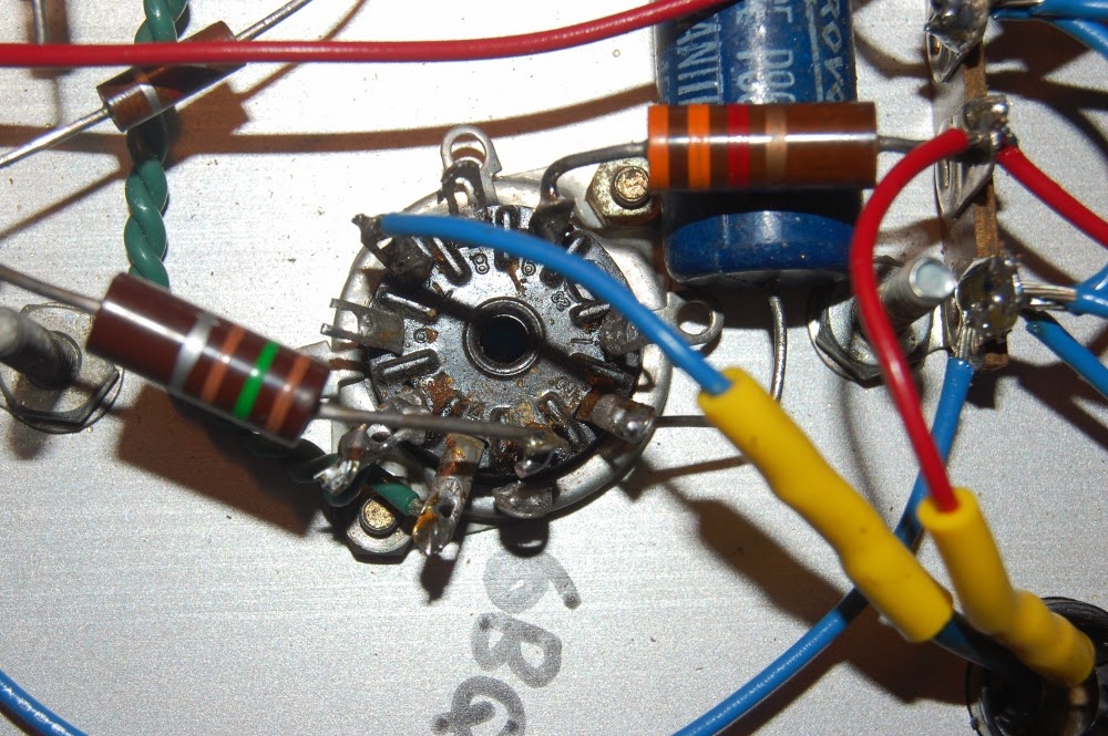
Here it is evident that I am using previously built components, and did not exert a lot of care in cleaning the vestiges of whatever this used to be. It's a 6BQ5 single ended power section now, please ignore any other disarray. AT LEAST I DIDN'T LEAVE REMNANTS OF WIRING!

I'd like to note that while the power amplifier stage is pretty much lifted directly from the Kalamazoo, the B+ power supply feeding it is a choked configuration more in line with the 6G15. The single ended amplifier stage feeds an output transformer coupled to a spring reverb tank.

The return from the reverb tank is seen here, direct coupled to the low numbers side of the 12AX7 gain recovery tube. This feeds a tone control connected to the high side of a mix control to output. High number side is a cathode follower dry feed taken from input jack, which drives the low side of the mix control.

Depicted above is the aforementioned tone and mix controls. Allow me to name off the imbroglio of capacitors, as there is no single photographic vantage point that could make sense of this mess.

The burnt sienna .03@600 CDE to the left is the DC blocking input cap for dry stage. Grid is elevated ~ 100 volts or so, and this fine capacitor is what keeps that off my pickups (or transistors, opamps, transformers, whatever.. outboard spring reverb will see more duty than just guitar).
The cyan/turquoise .1@400 is the DC blocker at dry cathode follower to mix pot (at right).
The .01@400 Sprague Black Cat is my reverb recovery section coupling cap to tone control. I think this should actually be a .1, that's a mistake (see if you can spot two more amidst these pics!) but I guess I'll leave it be unless reverb return sounds too thin.
The black .01 disc cap is the tone cap from control to ground, doing what it can to shunt ALL my signal away since I botched the coupling size.
The domino mica cap is a 500pf coupler from tone wiper to mix. I figured I would double the 6G15 design of 250pf here, because, well, you know, I like a little bass. Hahaha, apparently this was a wasted effort. I'll revisit this later. We're not done yet.

Before anyone pipes up about it, yes, I am aware of capacitive coupling, lead dress and ground loops. Thankfully I'm okay at (read as: used to) working in tight configurations, what with the rework I have in store.

The unit is going to be a controls on face, at bottom type of configuration (ala Marshall heads); so this is the natural finished stance of the chassis. Rear support is not going to be via standoff, it will be supported all sides by wooden runners.

So, with everything more or less squared away I set about the initial slow warm up on a variac. Something, however, was amiss. My voltages were way off, B+ being abnormally low. Concern with a short circuit proved unwarranted. Everything tested out okay, it was just that my B+ leg was reading roughly 10% of expected.

I had tested this transformer prior, and it was concluded to be a ~500 volt center tapped secondary. You know, because I measured it. Having the luxury of an uninstalled identical transformer I conducted the measurement test again on a part out of circuit.

Imagine my surprise when it turned out the high voltage secondary of my chosen power transformer was in fact delivering only ~50 volts across the windings! DECIMAL POINTS MATTER.

Above is an example of finished fitment, tight gap between the tube and chassis. Too tight? I'd probably bevel that on a production unit, but this is not, so..

Anyway, I'm wary about trying to fit enough discrete voltage multiplier stages to make use of the 50 volt center tapped PT work, so I'm thinking about piggybacking another transformer in there, either something with a proper B+ right out of the gate, or a step up I can drive with the 50 volts (I think a 120:24 volt transformer may work nicely here). Sadly, I couldn't find a correct voltage range with identical mounting in my piles, so the fix may wind up being less than visually perfect.

Of course, it'll all be encased in a cabinet anyway. Stay humble!

Saturday, January 19, 2013

Where was I? Oh yes, I had polished the legs of all analog ICs in channel 8, reinstalled them, and then observed function. Success!

So naturally at this point I disinter all the patina laden ICs in channels 5 through 7, clean them up, reseat chips, reinstall channel cards and apply power.

Nothing. Well, unless you count the full meter deflection of 5-8; audio certainly isn't passing through any of these.

That includes channel 8, of course, which, by my own observation was just passing the first tier of functional test and literally has not been touched since.

Pull card 5 (again, if I was thinking clearly and weighing out all the evidence this step would have been reduced to one selection, but I was at this point a touch flustered). Power up, 6-8 pulse the VU. Power down.

Leave 5 out, pull 6 & power up; 7 & 8 pulse the VU, power down.

Pull 7 & power up, channel 8 shows a minor bump on the VU and now passes sound. Power down, reinstall 5.

Power up, channel 5 shows a minor bump on the VU whereas channel 8 does not deflect at all, both channels pass audio. Power down and install 6, which completes the pattern as expected.

Channel 7 contains a problem that was pulling down channels 5-8. Having my quarry fixed, I now begin to puzzle this out logically, and based on the power rail observation made previous I begin with measuring the rails for shorts. -15 volts to common measures 0.8 ohms.

Ah, the dogs, they have your scent. All integrated circuits are pulled, the short remains. Of course it wasn't going to be that easy. I pore over the schematic for all points tying directly to the negative rail, and choosing for now to ignore resistors narrow my focus to a dozen or so parts and begin to pull them out, one at a time to determine which part is failed.

Next time, I'm going to start with the caps. The dense two sided PCB has made me out for a bungling idiot, and before I actually pull any traces that are important (this was just an insert) I shift my method to cutting.

Which, while destructive, limits the destruction to parts at hand. I'm still exacting far more destruction than I feel I should on this simple task. This particular component was just fine before I came along, WOOF.

Having ruled out transistors I then focus on capacitors. C4 here is the problem, a Matsushita 1 uf @ 35 volts, it's marked as being polarized. Tantalum? Odd package, I can get those values in a similar dimension in ceramic, which is my plan.

Of course, I threaded up a reel of tape and learned my record levels have been killed (previously 3 & 4 had recorded well), now everything reads high to tape and plays back low, with the exception of previously recorded material. So now I chase a common point in all channel recording. I'm thinking bias as a starting point, have mercy.

Friday, January 11, 2013

Having temporarily ruled out a logic problem (which seems logical in retrospect, since I have observed the status LEDs appear to be driven from the state of the channel card itself and not the logic commanding the card), it was back to troubleshooting the machine as a complete unit.

While I had all the cards pulled I naturally brushed out cobwebs and hit the edge connectors with contact cleaner, so it was only logical to fully reassemble the unit and see if a good cleaning did the trick. No change.

Next step was to narrow down point of focus. For brevity sake I'm just going to observe the behaviour of the VU meter on power up and power down, since in consulting a friend who has a very functional version of the same machine I was informed that meter deflection of any sort in response to the on/off switch was unusual. So I swapped cards 4 & 5.

No change in 5-8 deflection at power up, though now #4 was pegging the channel 5 meter as a steady state while the natives along 6-8 returned to zero. Quickly power down & confirm card was seated correctly. I pull channel 4 card & channel 6 card to compare, they are, for all intents & purposes identical (beyond the fact that they carry factory stickers indicating their home channel).

I then install the channel 4 card into channel 6 slot, placing channel 6 card into channel 5 slot. 5-8 full deflection tap and now channel 6 is pegged. Power down.

While channels 1-4 have not been considered suspect, due to them actually functioning (and bolstered by the fact that channel 4 has in fact recorded to tape and passed the listening test, which I would like to think is pretty stringent). I then swap Channel 3 with #4 in 6. 5-8 full deflection tap and channel 6 remains pegged. Power down.

At this point I overlook a step that could have saved me a little time and effort. It should be obvious that I am not a factory trained technician, nor am I intimately familiar with the workings of this machine (getting there). I'm pretty much working in the dark with my empirical approach and a set of freely downloaded schematics.

Make no mistake, I am brimming over with a sense of gratitude toward the good people at AnalogRules.com, for without these highly useful documents I would quite simply be fucked. However, there came a point at which deep circuit analysis turned into a hide and seek sort of affair due to a lack of clarity in the scan. So yeah, I'm pretty much just making this process up as I go along.

So, my next step was to remove all the cards, set 1-4 aside as known functional and install 5-8 into the 1-4 slots. Anyone care to guess what happened?

Nothing, unless you count 1-4 meters deflecting fully on power up. I run signal test to confirm a complete lack of function.

Based on this observation (and brownie points to whoever catches my mistakes here) I shift focus on channel cards 5-8 themselves, and ignore for the moment the steady pegging of the low number cards in high number slots (another hint). I had deemed the probability of discrete failures on the four cards, right next to each other, as highly unlikely, but it's worth a look anyway.

All my analog ICs are looking a touched charred (this batch is among the cleaner looking). Granted, there's patina on the analog ICs in channel 1-4 too, but I'm not paying them much scrutiny, as they are not problematic. Incidentally, all the digital ICs are looking quite fresh & nickel plated, so it's a metallurgy thing, perhaps there's a high content of silver in the legs. Whatever.

So, channel 8 is my guinea pig, I've plucked the chips and go to work.

600 grit sandpaper and a little time, before and after shot here.

The ICs cleaned up pretty well, flushed the sockets with contact cleaner, reseated the ICs into channel 8 card and sink that channel into channel 8 slot - with no other cards with the exception of the logic control. Power the machine up. Minor deflection on channel 8. The card passes sound!

It is at this point that, flushed with a sense of progress and ready for a break I happily report to my magnificent and wonderfully patient wife that I've finally secured what appears to be a solid lead amidst a convoluted mess of red herrings. HAHAHAHA, oh the humanity.

Saturday, May 05, 2012

In the days since I updated last I have brought this beast on line.

It has not been without struggle mind you.

Phase 1: rebuilt bias dropping circuit to reflect values close to those originally published for the 7027A configuration of the amplifier (130K dropping with a 15K straddling the bias filtering caps, 10K trim on top of a 56.1K to ground). This is pretty much where I was at end of April. Netted a nominal 4 ma idle current on three of the tubes, whereas one read no current. I was busy checking voltages on the no current tube when my meter gave up the ghost (shunting enough voltage to ground to increase at the wall current consumption by a half amp). Meter no longer trusted for voltage work, everything is shelved in await for a replacement.

Phase 2: knowing that 4 ma idle current is indicative of an over biased situation, regardless of potential wiring error on my part, I remove and replace the 130K with a 150K per later revision. In doing this work the tubes are removed and replaced. All four tubes JJ E34L, one pair had been in a red plate runaway situation and was easily identifiable by the darkened paint on the envelope; darkened pair inner, non-abused pair outer - as I've always been installing them.

Phase 3: armed now with a new meter I ease the amp up and read nominal idle current in the 20 ma range, except at the one outer socket - which has switched sides......

Break out tube tester and confirm that one of the non-abused E34L is in fact useless. Dig through the stacks to come up with a handful of used EL34 & 6CA7.

Phase 4: the next value of 2 watt resistor I have is banded 170K and reads at 200K, all three 170K resistors read similar. Fire the amp up and read in the 50s for the E34L and lower 60s for a pair of Sovtek EL34WXT I have sitting in the outer sockets. No red plate at idle just yet, though I realize this is ranging them a bit hot. I plug my Tektronix RM503 into the extension cab socket (modified to be wired in parallel to the main output, not a switched series stack) to have a peek at waveform while the 4 ohm dummy load dissipates power and observe a tinge of orange on the Sovteks. Pull the meter out and read well over 100 ma. Shut down the amp and pull the Sovteks, which tested high on transconductance compared to the E34L I already have installed (which have served as the baseline changes to the amp over all).

Phase 5: find a 174K 1% of sufficient girth and swap that in to main bias dropping resistor slot. Test out the pile of tubes for something closer to the level of the E34L. Sovteks test high, the Sylvania 6CA7 is off the charts, a pair of Matsushita 6CA7 weigh in a bit lower. These are installed as outer pair. I've observed a roughly 7-10% travel in current adjustment with my 10K bias supply pots, enough to trim in an already similar quartet, but proving insufficient to balance out dissimilar tubes, which remains one of the goals.

Anyhow, with the 174K I can level the E34L out at 42 ma, while the Matsushita 6CA7 are stuck in the upper 20s. I'd rather err on the side of too cold for the moment and finish up some adjustments so I can house the amp and actually get to listening tests. This entails adjusting this phase inverter balance pot so I plumb the dummy load and o-scope into the speaker jacks and run a sine wave oscillator into the input, grab the knob and give it a twist while watching the trace on the screen.

This process is not incredibly helpful; as the adjustments only seem to have bearing on amplitude as opposed to balance of waveform, though to be fair the waveform could be out of balance and I'm just missing the baseline. I crank the volume dial up to a point where I can hear the frequency rattling the guts of the amp/dummy load (which is getting warm) and observe a clipped output. Though clipped the output still looks balanced, so I ramp the amplitude up to the point of ringing the waveform, adjust the balance pot to smooth that out - have a glance at the amp which is groaning a little under load to observe the quartet of outputs well into the orange.

Flick the power switch, which does nothing. Kill power at the variac, walk away and eat lunch.

Fire the amp up without adjusting anything, read low 40s & high 20s at idle. Plug 4 ohm speaker cab in and play a little while watching current draw. Normal use has draw ranging from the 50s to the 80s, though the amp is in no way being run wide open.

In the end the phase inverter balance was adjusted by ear (I reached for the loudest position, extreme swing on either side fell into cut-off) & the amp is buttoned up for observation while playing with standard sources. Being able to read current while playing will allow me to avoid running the amp into self destruction.

So, still not through the hazard territory, but well on the way. I need to bring B+ down to original values (my wall voltage is a touch higher than 1969s) which should push the point of runaway out even farther, and I think upscaling my adjustment pots to 20K might be worthwhile, but lower on the priority scale.

Monday, March 28, 2011

No work surfaces make me cranky. I'm still on the Intersound Mini-Six. My work surface for this particular project up to this point has been, I shit you not, a Hallicrafters S-53 sitting on top of the Lafayette U-50 standing on its side.


Here's an overlay of the circuit components I pulled out of the malfunctioning negative side of the +/- 12 volt power supply.


Here's a pulled trace from extracting the master volume control, not really an impediment, just annoying.

In plotting my approach to repair this unit, I've opted for simple regulation in the power supply. A regulator, instead of a discrete circuit. I'm going to learn what I can from the original circuit, but as a matter of course I'm taking the easy way out for now.


Turns out I didn't have TO-92 regulators on hand either, so the legs of a TO-220 are trimmed to fit.


Next step should be obvious..

So, I slapped a voltage regulator in and fired it up.

Lo and behold, there is now a negative voltage! However, it is less than 12 volts; and establishing a negative rail has pulled the positive rail down by several volts as well.

It was at this point that the ludicrousness of sitting on a box on top of a milk crate while working on a "table" that essentially boils down to a balancing act really sunk in. All tinkering is in stand-by while I sort out space issues.

Take care of your work-bench.

Friday, March 18, 2011

Were TO-92 voltage regulators difficult to source in the late 1970s?


This 2N4403 is in the regulator hotseat with roughly -22 volts at collector, -16 at base and nothing at emitter. The 2N4401 on the positive rail shows much more reasonable voltages of 13.4, 12.6 and 11.9 respectively.


I'd like to know who drew arrows on this unit, and why. The arrow shown is pointing at the leg on which there should be voltage but is not.


More cryptic hints topside.


I'm tempted to gut the regulator sections and populate with 7812/7912.

Thursday, March 10, 2011

I'm preparing to briefly touch upon the ANALOG vs. DIGITAL debate (oh so tired a discourse), guess which side I'm going to take.

So, as determined last time I had a look at the Tek 556, it would behoove me to focus only on circuit elements that are upstream of the power switch, narrowing my attention to the mains filter. Easiest test was to read for continuity across the AC legs of the power jack, at the highest range I watched my DMM read lower and lower resistances. Digital meters send a pulse out one probe and weigh the voltage drop vs current delivered into the completed circuit to determine resistance between the leads. In this case the pulse was charging the capacitor meant to shunt high frequency line noise, so as the cap slowly charged the perceived voltage drop was less and less, delivering the false reading of a lower resistance. Clearly, sometimes easiest is not best, or even good.

Time to start sniffing around for a decent analog meter.


While it has been over a week, this hole retains traces of the odor of failure.


The inlet cavity of the Sprague filter also appears to have seen heat in the past. While this could be patina that evolved over the past 45 years, I don't trust this part, so it will go.


I highly doubt I can find another one of these with ease, and if I did I'm betting it would be of roughly the same age, meaning it would be "vintage" and there'd likely be some sort of premium on top of the decrepit part. No thanks.

Seems the easiest path before me is to build in a modern power conditioner in the space previously occupied by the large can of the Sprague. I toyed, for some fraction of a moment, with the idea of building the circuit inside the Sprague can, but the PITA factor coupled with not knowing what's inside the can (1966 was within the polychlorinated biphenyl era) sobered me up.


Not reusing the Sprague component will demand I change my hardware a little in order to mount the voltage badge, I'm thinking nuts.


Spot the high voltage wire!

Tuesday, January 18, 2011

Received my ON-Semi MJ21195/96 power transistors for the Soundcraftsmen power amplifier late last week and slapped them in over the weekend. In a wholly unscientific manner I opted on the MJ21195/96 because the response curves tapered in a gradual manner and the ramp up to roughly the 50% current output appeared peppier. Plus they were cheaper, by 57 cents each. If the amp sounds like shit when I'm done, exploring the other output devices is within my capabilities.

That would, naturally, only happen after a recap and some other tweaking the good people at audiokarma.org have spoken of.


This, and a pair of pliers to grab and twist the shaft, is how I reached the rear screws without tearing this thing completely down.


As I wrote a while back, the rebranded TO-3 transistors were less than informative in regards to determining which of the 2SB554/2SD424 pair carried which cryptic alpha-numeric stamp. Direct measurement to determine the orientation of "diodes" on surviving devices was the simplest route to identification, here we see the unobtanium "5A" PNP (2SB554) being replaced with current production devices.

Replacement surgery went well, next up looks to be replacing the differential pair to shed some DC offset on the outputs, but before I go that far I aim to secure a copy of the service literature on this amp to assist in avoiding any pitfalls. Why yes, I probably should have had that from the beginning.

Tuesday, January 04, 2011

I've depleted my stash of basket case amplifiers on hand, so it's time to crack the case on that Peavey 260. Don't worry, there are plenty of basket case amplifiers and so forth that will be looked at in the future, I just have to dig them out.


Access to amplifier transistors is about as easy as it gets. My original hunch on this amp, that carried 39 volts DC on the signal pin of the output jack, was that of a failed power transistor. These all tested good, so my suspicion has been downgraded to failed driver pushing the output into saturation or good old fashioned funkiness with the connections.


These sockets may have to go. I'm weighing out my abilities to polish/inspect the connector surface, while my mind keeps interjecting "remove and replace". Honestly, circuit analysis while charged seems pointless while these sockets are cradling the pins of the output devices. I should also mention that the pins on the TO3 transistors are also less than pristine, almost as if something has been electrochemically corroding them.


The power supply capacitors are clearly in need of replacement, physical distortions are evident.


I also don't approve of the mains ground termination, pictured here tying in with the sleeve of a speaker output jack. This makes for a completely mechanical joint, relying on the nut that holds the jack in place to complete ground. I'm guessing, if you're reading this, that you are familiar with these nuts of which I speak. They wouldn't be my first choice for a safety feature, but this isn't the work of Peavey, it is a retrofit to three prong from the OE two prong power cable. Better than nothing I guess, I'll still change it to satisfy my standards.

Thursday, December 09, 2010

Eugene Noise Fest transpired last Saturday. It was packed into a single day (taking place in a house that was no longer 100% tenant friendly) which turned out to be a long haul. Always happy it happens, and I'm always happy when it's over.

I actually brought my camera, mainly to take a gear porn shot of my set-up in front of my sound system, but by the time I went on (over four hours behind schedule) I was in a no bullshit frame of mind and didn't take a pause for sightseeing.

The PA system is described as follows: (I'll get around to taking set-up pics, eventually)

Fender MX-5200 mixing desk feeding a Rane AC23 crossover with points set at 120 hz and 1K4 hz.
Low end fed to a Mackie M1400i high passed at ~38 hz feeding a McCauley 6242 and a Carvin HE15 (rebranded Eminence as far as I can tell) in the folded bass horns as described previously.
Middle range fed a Crown Power Base 1 driving a pair of JBL D130 loaded in Altec 828 cabinets.
High range fed the EICO HF87 driving Altec 288 compression drivers bolted to JBL 2395 horns.

At least, that was what was hooked up at the beginning. From the get go the left HF driver was hanging out in the realm of the non-existent. I chased a red herring around the speaker assembly (involving disassembly on the stage) because I had done a little work on that driver earlier that day only to conclude that the trouble was stemming from the amplifier (to be accurate, the channel of the amp I'd worked on previous as well). I begrudgingly swapped that channel out for one side of the Heil 400 which was my supporting backup amp. This entailed moving from a transformer coupled 35 watt tube amp to a direct coupled 400 watt solid state amp without speaker protection. Nervousness did ensue. But having no back-up HF drivers, the early (1950s I think) Altecs had to go in. To be fair, the 16 ohm load of the compression driver really damped the power output of the sand amp, and in the end everything played nice there.

Sound was still off on the left side. This was narrowed down to a non-functional main (middle range). I had, in preparing and packing up for the show, considered pulling some spare JBL drivers for just such a contingency. Of course, considering and doing are not the same thing. So, in order to have full range response on I hauled ass to the practice space, pulled a pair of JBL K130 from a 2x15, and set about climbing behind the stacks upon return.


This is when I reaffirmed my deep seated hatred toward slot head screws (22 of them were holding the back panel on) while working in a small dark corner. This entire process took about 45 minutes, from leaving to fetch a replacement driver to having it installed, during which the longest set of the evening transpired. Oh, and I became reminded to plug the speaker cable back in after it didn't work right the first time.

And thus, sound was delivered in full and the speaker side of things gave no further problems and sounded good (though I plan on setting the low-mid crossover point a touch lower next time as the bass drivers got a little shouty at 120 hz).

But wait, what's that smell?


Redplating tubes are the easiest thing in the world to spot under these circumstances, and it only took a glance into the amp cabinet to source the origin of the burning odor. Of course, at this point I am morally obligated to NOT shut the sound system down. We're fully running behind and I've done enough damage as it is. The pair of output tubes in runaway are in the problematic channel I've already bypassed, so without further ado I knock a few volts off at the variac, borrow a glove (happened to be a left hander, which was of no concern at the time) and set about pulling the tubes hot. The gloves, which had those rubber grip bumps, immediately began to emit smoke. I do hope this offered entertainment value to everyone observing the events. Gloves saved my skin, absolutely, but they did not make handling the tubes comfortable by any stretch of the imagination, so with a smoking hand I made the snap decision to lay the tube atop my TOA mixer to cool. Repeat for the other, and the rest of the evening my side went okay.

I made a single rule to follow this year at ENF: "If it requires soldering to fix, it is broken and we're going to live without it". I'm happy to say I held fast to that rule and everything came together, unlike 2008:


Photo credit: Matt Brislawn

Huge round of thanks to Doug Theirault, for use of DI boxes which eliminated the ground loop hum, and to BLOODSON DRIFTER for use of a glove, without which would have caused me much continuing grief.