Showing posts with label mixer. Show all posts

Sunday, July 20, 2014

It began with a feeling of dissatisfaction with my over all sound quality whenever I packed up some gear to play a live show. At this point, it's probably best if I expand on what I mean by quality: it's not a term that I am using to describe low noise, astronomical bandwidth, and remarkably low distortion figures. I have enough of that shit with the mass produced junk that birthed these complaints to begin with.

I should also point out, to the internet traveller that may be reading this as result of information hunter/gatherer forays (as opposed to the handful of freaks that know me), that in my application of these tools I am not striving for faithful reproduction, vintage tone or many other aspects in the array of audio qualities that drive gear obsessed frenzies of human endeavour. What follows is decidedly NOT a page to follow if you are hoping to recreate a nuance to fit into useful applications of gear in a client based environment, or where there may be a self professed audiophile or two creeping around the woodwork. There is no deeply entrenched philosophy driving this beyond my trying to use only what I had on hand

I also realize that from an electrical engineer standpoint the following may constitute a load of bollocks the likes of which all upstanding individuals in the industry have been striving to wrench into non-existence for about as many decades as mathematics have been applied to the craft, which, unless I am mistaken - is all of them. I realize my methods herein are laughable, and I assure anyone that were I not building this for myself I would not opt in on the sort of short cut that might make you cringe. Unless of course I was directed to do so.

So yeah, that preamble amounts to a wordy "yeah, yeah, yeah, I know" to the quantity of errors that I know follows, and furthermore to the quantity I didn't catch. Enjoy.

With the Autogram AC-8 that fronts my studio as a reference to the sound quality that got me spoiled to begin with, I decided to emulate the largely passive transformer coupled mixing network feeding discrete operational amplifiers. So this build will play out like a mystery, start at the end and work my way back. I selected the Jensen 918 as the platform I would build from, mainly because it was the first one I happened across that contained a sufficient amount of documentation.

Clearly depicted here is a complete disregard for thermal coupling, though I did strive to keep signal flow as "direct path" as I was able.

Of course, without supporting circuitry, the op-amp was somewhat underwhelming. Thankfully the documentation linked above addresses everything you need to build it Note, if you want to use a +/- 24 volt supply - you'll see reference to some value juggling on a page that doesn't seem to exist. I've had no trouble running mine on +/- 24 volts having swapped out the 27K with 47K.

I wound up slapping blocking caps on input and output because either I built it wrong, or it is designed to supply +22 volts on output, and +10 on input. If I built it wrong, I don't want to be right. Coupling caps sorted out the DC element out of respect for neighbouring stages, and the output leg with the larger carbon comp 33 ohm load is slated to feed a pair of output transformers (with 2N3904/6 complimentary pair, yes, I realize heavier outputs would do more lifting.. performs just fine for my application. Distortion capability on this board is delightful, I trimmed it up to the point at which it was clearly going into class C, then scientifically dialed it back to the point at which the audio filled out.

So, haphazard summing section in hand, I needed to sort my inputs. The aforementioned Autogram is a stereo in/out desk, and as such I have been somewhat hindered in the ability to pan mono signals without the introduction of another mixer - which paves the way back to sentence one.

GOTO 10

I don't really recall even giving the idea of a passive front end with pan any thought at all. So, right out of the gate it had to be active, and in line with my build so far it had to be devoid of integrated circuits. Enter the schematic for a Neve BA284, I worked up a layout that could fit eight onto a single proto-board.

I knew it was going to be tight, so everything went on in upright configuration..

..and when I was squeezed off the front, I resorted to stuffing from the back.

Everything is still pretty reasonable and accessible, though I am going to have to tie wires into the floating pigtails in the middle section.

Same level of progress, just another angle to illustrate my complete disregard for long lead insulation.

A moment contemplating the two, wondering what I've gotten myself into.

Who needs modern compact electrolytics when big fat dipped tantalums are on hand? Wanna argue capacitor merits? I already know the tantalum is WIDELY poo-pooed by the golden ear community (GOTO 20). Again, my build, besides, I've heard other audio egg heads remark that early Neve sound comes partly from the use of tantalum, and that his application of them biased the capacitor such that many of the distortion characteristics that many find distasteful were designed out.

Whatever, I'm regurgitating stuff I've read on the internet. I don't know. Hell, I don't even know if the schematic I used is in fact a Neve as it is passed as. Could be a heat control for a toaster oven for all I know. The big orange caps are pretty, justification complete.

Gee, maybe I should have tested this thing before going this far?

Re-work will not be a breeze.

So, once wired up for test here's what happened: Channel 1-3 passed audio, 4 was dead (bad mid 1973 tant cap on input - replaced) 5-6 passed audio, 7 was dead (solder bridge, easy fix) and 8 was very low volume (less critical solder bridge).

On to connecting the two. Currently the 8 channel block feeds 1:1 transformers, which feed a single pot passive pan control which feeds a dual gang audio taper volume control feeding the stereo buss to 918 opamps.

More blatant disregard for insulation.

HANGING FREE, READY TO SHORT.

Input block in, those ugly holes will be direct outs from the inverting output section built into the BA284 clones (hahaha, they are as much a clone of the BA284 as Frankenstein's creature is a clone of a human being, but I digress). Fun fact, the jack connected to the blue wire is an open frame TT connector, it provided me with a little more first hand experience in reworking this free form construction. A lot easier than I had expected.

Wire tie in about to be squished, then soldered.

Of course, at this point I'm working against the fact that I've got a show later in the day, and I would really like to use this thing. Top shell, current function largely wired.

Baseplate, same.

Quick connects and screw terminals allow for ease of disassembly.

It worked fine. Only the fundamental functions are installed right now, but everything goes together like legos and inserting future sections will not require anything too extreme. Current duration of work so far: July 3-19.

Tuesday, January 22, 2013

I drove a couple towns over and picked up a Gates Studioette M-5381 yesterday. Let's have a look.

Solid logo, I haven't yet put a fine point on internal date codes, but the manual was printed in 1962.

Only 24 inches wide, seated in my work chair. I'm going to have to make a better place for it & will follow up with a better front panel shot later.

Recessed VU meter, quite modernized styling over the RCA BC-3C from the same era.

The front panel of this unit has escaped the rough hand of modification. There are some additional holes on the sides, but for once the face is left alone (which reminds me, I really need to post pictures of the basket case RCA).

This is where the serial would go these days, curious if there are identifying marks inside that would point to record with the manufacturer (not that it would do me any good).

GUTS. Hinged front is the control surface. Moving into the chassis, lower left is a pair of microphone preamplifiers, each with input and output transformer (albeit somewhat puny ones for the era, no need for 5 hz on AM radio, thanks) and room for one more. Shifting right we see a solitary UTC A-21 doing duty on line level inputs, keeping those voltage regulation tubes company. Continuing on to the right there is the program amplifier with three pentodes and a dual triode, the circular transformer being input and the larger rectangular transformer being output.

Shifting to the back row, at far left there is the monitor booster amplifier, 150 ohm balanced line input to 12AX7 pushing... a push pull 6BQ5 monitor amplifier which wisely has its output iron bolted to something more substantial than phenolic PC board, and on to the power supply.

Here's a closer look at the power supply, nothing unusual: mains transformer, rectifier tube, a couple of chokes. The output transformer for the amplifier stage is in close proximity, which will confine power hungry pulls on the B+ well away from high gain stages. Those two relays will probably go unused. I haven't seen a power switch on this unit yet, I will certainly be paying this section some scrutiny when update time rolls around.

Staring too long at this may make me delay diving right in. No! That's the wrong angle, this looks like meditative fun to sort and resort. Wind and dive.

Conductive plastic or mechanical fortitude? I know which direction my preferences lie.

I found the maker's mark in the Daven cap interesting enough to photograph, given the amount of scuffing (original as far as I can tell).

Apparently the #3 gap is standard from factory, designed in room for expansion. Who knows what will take place there in the future? Since I have the manual, and having roughly 52 hours notice of collecting this device spent some time fruitlessly searching for a digital copy (of which I could find none) I intend on scanning up a pdf and sharing that with the digital universe once I get a chance.

Here's a closer look at the preamps.

A truncated shot of the program amplifier (I think I'd term this summing section, but since it was named from the factory I'll show it a little respect). Observe the dirt build up from the right end..

Closer look at the monitor booster.

Yes, some clean up is in order.

...

The fan was added post factory, it would have been a good idea to put a filter on it. After seeing this I'm pretty sure the fan is getting the heave, I plan on undervolting the mains a couple percent, which should rein in the heat a bit. Honestly, having looked at the underside of the lid I don't think excess heat was ever really an issue.

Exposed tabs! SO much nicer than having to work through a punch hole in the chassis, this one's a keeper for sure.

Saturday, October 27, 2012

After over a year of riding around in a box the Ramsa WR8210 was put back together.

Evidently I've some slider caps to hunt out yet.

Living in a box didn't do the mixer a whole lot of good, as evidenced by the bent PCB for channel seven. The wear & tear is limited to aesthetics, and thankfully that's invisible once everything is buttoned up.

I either forgot to count up the caps in the headphone amplifier circuit, or they've been misplaced. Since this is a less than critical point I ignored it (along with a couple in the LED bar graph driver circuit) so I could reassemble the mixer and move on to the next thing.

At some point in the future I'll wrap up another year + old project!

Wednesday, March 28, 2012

I'm slated to commence on a recording project this evening, so it's high time I get around to recapping the Langevin AM-301.

If anyone reading this has a spare couple of those red Rolo looking slider caps, I'm interested.

Another low parts count device, my favorite!

To the right is an upsized 33-50 (was a 25-25) CDE and 4.7-63 Spragues, but they are nigh on identical in appearance to the Nichicon caps in other values I procured. I miss the days of manufacturers celebrating their independence with unique and ugly colors (you know, when they made the stuff themselves..).

I decided to draw the line at recapping 4 (BEAD), retaining a pair of original (CF) and the pair of previously modified (HG, by an unknown tech at an unknown date) for comparative purposes. I've seen pictures of this mixer as a set, with EQ, limiting, etc, and am speculating that the traces that terminate at the end of the PCB can plug into additional modules (of which I sadly have none).

While the picture does not reflect this, I have recapped the master summing cards seen here. I have not yet messed with the 100-50 CDE Beavers, as to do that in a non-half-assed manner will entail actual disassembly (as opposed to actually reaching over and pulling open the flip up panel). I might be a lazy asshole and clip those caps out, loop the existing legs and install the new caps that way, but just typing that out made me cringe so that's probably unlikely. It will probably wait until I dig in to replace the channel 8 slider, unless malfunction forces me to tend to it immediately.

Power is single pole 48 volts DC. Makes it tempting to implement phantom power, though I could probably build up a small phantom power breakout box to piggyback that 6 pin Jones outlet with a lot less hassle and more ease of use. I do like the abbreviated "cue".

Saturday, January 21, 2012

Gave the Fender MX 5216 a quick run through, cleaning switches, as they were acting dodgy and this unit may be rotating out into a new home.

Working surface, after I'd dropped the PCB off each sub-section. While I had open metal, I took the opportunity to wipe it off.

Original buildup.

Each sub-section houses a horizontal circuit board with duplicate circuits, lots of ribbon cable.

Everything is pretty easy to get at, and through hole construction. Built in the mid 1990s, when miniaturization was really getting a toehold.

I'm guessing this could benefit from a recap. I'm not tackling that one right now, but at 10 caps a channel it doesn't look too terrible even if the pots outline an obstacle course.

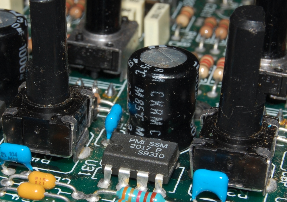
Per channel breakdown: first stage is a SSM2017, TL072 is seated in the EQ section, NE5532 in the Aux send section, MC14053B in the output routing section and an NE5532 acts as post fader recovery. The summing section is populated almost entirely with NE5532.

When I bought this in ~2007, two of the input channels were non functional. As it happens, the input trim control pots had popped apart, it was a matter of realigning and tensioning the metal legs to hold it together.

One of the ribbon connectors popped free unlabelled, and since several of the header connectors at the board are not populated, I had to reverse engineer the connection. Reading continuity at Aux send 1 & 2, it became reasonable to conclude it belonged at the Aux send 1 & 2 block.