Friday, December 31, 2010

The dryer is my auxiliary work bench.


Burning in the recapped Princeton with the variable AC/DC power supply I spoke of a while back.


I'm excited about the ammeter on the front panel, makes me wish this unit was good for more than 1-2.25 amps (doubt I'll push it beyond the range of the panel meter). The only modification I exercised on the unit was removal of the 10 watt 150 ohm resistor strapping the DC output jacks. It would heat up CONSIDERABLY at a fraction of the range I will be using.

As far as I can tell, the reason it was there in the first place was to drain off stored charge in the capacitors, as they don't have resistors to drain voltage when powered off. I'd rather install a high value resistor across the cap itself as opposed to keeping the low value space heater hanging off the front panel.

My plan for the immediate future is to process a few unknown amps and form up a component shopping list to exact repairs.

Wednesday, December 29, 2010

Recapped the B+ power supply of my 1973/4 Fender Princeton last night. This is the amp that had sat in a shed for a while and sounded anemic as hell in a raspy farting through a cork wall sort of way. The main problem was not a failing speaker as the seller thought, but a lifted ground reference in the phase inverter section that proved a simple fix. The amp was far from done, needing the logical next step: removal and replacement of 37 year old electrolytics.


Since the overall amp is so compact, I faceplanted the cabinet and used the upper rear baffle railing as my chassis stand.


Here's the original equipment, a Mallory axial 20MF hailing from the 43rd week of 1973 and a Mallory 40-20-20 multi-section can cap built in the 29th week of 1973 (you'll just have to trust me on that one).


Can caps that tie to the chassis require a nice solid structural solder joint that completes ground and secures the cap to the amp. For this, liberal application of heat is a thousand times better than trying to remove and replace a chassis pool with an underpowered or small iron. Here's the 100 watt Weller I use for chassis work in comparison to the variable temp iron I use for all other component grade work.


Of course, with a behemoth hot iron, all of its benefits in this single application are detrimental in every other way. Shifting of existing components that would otherwise be untouched is crucial; I've smelled enough melting plastic already, thanks.


This tab got the desoldering treatment, I'm about to bend the tab up and free this joint. The joint on the opposite end proved easier to just heat and rotate the can, shifting that tab out of the pool. Then it's just a matter of bending the remaining tabs up and dropping the old can out.


Ancient (remember, electronic eras pass faster than those of humans) solder flux reminds me of cerumen, and it too is generally undesirable when built up and can take multiple passes to get clean. Above shot is after a single scrub/soak pass of isopropyl, and yes the good people at Fender put that flux there in the first place. I have a few cotton swab heads full of the stuff if any collectors are interested.


Now it's ready for a new cap. I'm not concerned over the existing solder there and think of it as tinning for the new joint.


The replacement multisection is built by CE Manufacturing in the US, purportedly off the original Mallory tooling. In comparing parts side by side I find that very easy to believe, fitment was EXACT.


Somewhat hard to see, but the pull job here has a bulge in the center vent.

I bought the caps in reference to the schematic as opposed to referencing the actual amp, which is why the replacement multisection is a 20-20-20 as opposed to the 40-20-20 that was original. Frankly, I'm not overly concerned at the 20% drop in total capacitance of the power supply. It seems as if manufacturing tolerances of electrolytics tend to over build as opposed to under build, and I've heard people bellyaching about adverse effects that over capacitance has on tone. Seriously though, retrofitting a lower capacitance to follow the mid 1960s circuit isn't a life or death matter.


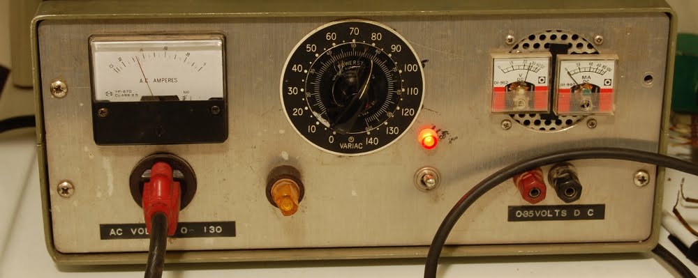
Here it is, ready to burn in slowly on a variac. I'm not in love with the recreation of the original joint at the head of the axial cap, but it seems solid enough and the other did last for 37 years just fine.. I only addressed the B+ caps for now as this is my amp and I expect to be in and out of it for a while; tinkering with the guts and getting it just right to my ear, so COMPLETE overhaul is less of a pressing issue. Once I've insured a solid electrical base, next step is to rotate through a pile of 10 inch speakers to find the best match for my practice and recording needs.

Monday, December 27, 2010

The past week and a half or so has been steeped in speculation and other mainly mental endeavours; so I'm digging up another long-standing project as opposed to some actual current progress shots, which is what I'd really prefer to populate these pages with. Elementary CAD screenshots and reinforced joint solutions are seem more boring than quips about blown woofers and asbestos bearing wire insulation, so without further ado I guess now is as good a time to unearth the RCA BC3C project as any.


I've plundered my binauralaboratories (out of date) write-up on these units for this shot taken in ~2001.


I'll upload some honest gutshot eventually. The mixer is essentially three pre-amplified microphone inputs, a transformer coupled input and a handful of low Z line level inputs feeding a two summed outputs, one tailored to line level feeds, the other bearing a PP 6V6 amplifier to drive in house monitoring systems.


I cut this card free a while back in order to scan the traces and facilitate tracing the signal path and recreating the schematic. This was right before I found a copy of the service manual, saving a lot of work.


I seem to have been suffering from focus related issues when I took this shot, but I'm sure the sense of a somewhat sparse printed circuit board is conveyed. Barring the modification of a printer to lay out diagrams and text, this is the level of construction I will be working with in the future.


This particular pre-amplifier module is in the summing recovery section that drives either the program output or monitor amplifier. The microphone level preamp card is similar, though it carries a few additional components to facilitate quiet switching. The first actual work on this will entail a power supply rebuild (squared, since there are two of these). Cost of a bunch of multisection can caps has been something of an impediment, but I can certainly dig into the rectifier and replace the selenium.

Friday, December 24, 2010

Here's a wire bearing asbestos in its insulation pictured above a typical plastic jacket wire.
Pulled out of an old wall heater that will become an enclosure to a build.


My suggestion is to avoid crushing and snorting BOTH types of wire. Asbestos occurs naturally and is everywhere, the main idea is to avoid concentrations of the stuff. After pulling the above wire it was put into captivity in a plastic bag and has not been allowed to rough house with the rest of the components loose on my bench.

Wednesday, December 22, 2010

This is my take on deploying car audio transducers in a real world sound reinforcement environment:


It isn't cheap if it needs to be replaced.

Tuesday, December 21, 2010

After yesterday's foray into the potential use of an abnormally large IC it only seems proper to consider this beast.


Analog Devices ADC12QM, a 12 bit analog to digital converter posed with standard 8 DIP IC for scale. This part has seem some better days, the pins sort of creating a still life of a centipede in motion.


I'm something of a Luddite in that I haven't fully embraced the digital standard as my shepard, so my comprehension of this may not be 100% accurate. This looks like a direct conversion ADC with a parallel array of bits ordered from least to most significant. Something I could feed directly into a resistor ladder DAC to return to the analog domain.

Since this particular IC may have been damaged in the bumpy road that was the final days of Northwest Electronics Surplus, I intend on building the supporting circuitry and hoping for the best. If this doesn't deliver there are other ICs that offer similar LSB to MSB pin out, though I may have to live without the huge package.

Monday, December 20, 2010

In researching the audio artifacts of spatial positioning, you'll find that sources a great distance away exhibit attenuated high frequencies in addition to the blurring of coherency typical of reverberation or short overlapping delay and a bit of low frequency distortion to induce rumble. This all makes sense, since a sound wave originating several miles away is going to travel over many folds in the surface of the earth, diffuse/reflect over objects moving and stationary, pass through variations in the air of temperature, density, suspended particles/humidity and mix with additional sound waves along the way.


These are Analog Devices 310J varactor bridge amplifiers, posed with a standard 8-DIP IC for scale. If the hand engraved four digit number is a date code, these hail from the 33rd week of 1973. Ever since laying my eyes on these I've known that I must one day integrate them into a build, exposed of course. My recent attention on the synthesizer project pulled these into the limelight, so I figured I should pull up product data and see what they are good for.


They claim a bandwidth of 2khz. The gain factor of this part starts taking a nose dive well into the subsonic, having tapered off to less than half the available gain once human hearing kicks in. It's like a mutant RIAA curve, that's hungry for woofers and human flesh.


Since these were obviously not aimed at the audio market they don't publish a frequency response graph. I realize that gain tapers to unity at 2khz, but that is not the same thing as a brick wall at 3khz, it will be interesting to hear how they sound. The generous low frequency amplification factor may work against me a bit, seeing as how these parts will be deployed in a modular synthesis environment through which direct current CV may be superimposed over signal paths at times. My initial plan is to feed the output of these into transformers to strip out the copious subsonics, It looks like the current delivery of these devices may not be enough to induce saturation of the transformer through application of DC and/or subsonics, so I might hide a small DC coupled amplifier stage within the module to open the possibility of CV driven transformer saturation.

Sunday, December 19, 2010

I think we're overdue for some gratuitous gut shot.


For this, we'll dig into a mid 1960s Cordovox accordian tone generator, essentially organ guts in a gig-able package.


In my preliminary searches I've narrowed the model down to a Cordovox CG, though I see no reference to a specific model on the number plate.


The complete system was composed of the tone generator bank (above); the power supply & amplifier, encased in a similar box with a 2x12 speaker baffle as opposed to the louver behind the grill cloth; and an accordion controller attached with a robust cable and multi-pin connector.


So it stands within reason that a switching bank feeding a couple DB-50 male connectors could put this thing to work. Sadly, I've no accordion controller handy to emulate.


Of course, use hinges on the functionality of the circuit. The deceptively simple control panel sits atop a convoluted wall of circuitry.


A bunch of 6X8 and 6FH8 in the oscillator stacks.


Oh yeah, much better. I believe those two lamps are there to keep interior temps warm enough to prevent condensation.


Oscillators look to be relaxation oscillators built around early integrated RC network packages and neon lamps. I'm betting this unit looks very cool in use (well, if you have X-Ray vision to see through that damn baffle).


Loads of prepackaged circuit components in use here, this thing would be a nightmare to do major replacement surgery on. A discrete point to point rendering of this circuit would be a sight to behold.


Since I'm more or less completely in the dark as to the feature set of this generator, I can only wager a few thoughts to the purpose of this hub or the leaf relay (which actually has 13 tines, the leftmost one being discolored or burnt), my main guess being that these parts support chords.

I had the bright idea of trying to bring this unit up on the variac yesterday, only to realize after the cracking the case that I needed the power amp section (which was left in storage) to supply power to this stage. This particular set came from the bad amp room haul, this was one of the more exciting elements of that haul, as I've had another pair of the same for a long while that had the tubes plucked from the oscillator banks making the possibility of tinkering slim.

Still, this one sits low enough on the priority scale to qualify as a casual project to be chipped away at with an air of nonchalance.

Saturday, December 18, 2010

Oh man. I've been using my recent (extremely sparse) downtime not to achieve progress, but to assess projects that have commenced and have not yet been completed. Specifically synthesizer related builds. With the exception of tacking on a few SMT package RAM for the WTPA sampler build, I haven't set a single bead of solder for synthesis in the year 2010. Heinous.


Here's my mostly populated Elby ASM-2 build. I need to do a few quick changes to the power supply branch since it'll be fed from an external regulated supply instead of providing its own, then it's mostly populating ICs, tacking in the odd transistor and installing tempcos.

Other mostly built circuits that are suffering from neglect:
Klee sequencer.
SN voice.
CGS wavefolder
CGS psycho LFO
and, IIRC some Buchla clone stuff.

I pretty much deadlocked progress due to my panel design. I have a very specific plan of attack and pushed the project aside to focus on the CNC build, reasoning that with the CNC I could then execute every aspect of the build in house (well, besides the PCBs which were premanufactured and all the components if'n you want to get technical). Due to consistent delays on the CNC front, I'm rethinking my approach and the revised plan is to draft everything up to the .dxf myself, then have the metal cut and milled by the professionals. Otherwise I fear you'll be reading a very similar post a year from now.

So I'm making the command decision to refamiliarize myself with these projects, source remaining odd-ball parts, lay-out vector drawings and hone my CAD skills into something more than horrible. Uphill battle, but at least there's a trace of a path to take.

Wednesday, December 15, 2010

Rolling back to the Peavey EQ-27, it would appear that, with exception of the sliding potentiometers, all front panel mounted controls terminate in failed solder joints at the PCB.


This just fortifies my dislike of panel mount controls soldered directly to a printed circuit board, I view this build method as nothing more than a labor saving tactic to shave money off the manufacturing process. It is not as road worthy as a wire loom that will flex as opposed to transmit the jolt of an impact to the circuit.


The pot legs are even worse, having wicked oil into the joint. This material will be removed prior to repair.

Tuesday, December 14, 2010

I'm currently at odds with my organization program down at the lab. I have a box of switches that is eluding me, and completed projects are starting to back up because of it. I figure I may as well add the EC power supply to the pile.


First step was to remove all components and hardware from the upper shroud. I posed it here with some of the objects I will be using to realign the sheet metal, notably absent: hammer, perhaps the most important tool of all. Okay, that tool is the mind, I'm still a bit miffed that the hammer wandered off during the photo shoot.


My initial idea of gently clamping stuff into shape was rapidly undermined by an array of deficiencies in the tool department. Seeing as how the project was under way on the living room floor and my ability to make new tools involved going across town, I reassessed my approach.


Roughing in the general shape by hand is satisfying, 17ga metal offers minimal resistance.


Shaping the corner is as easy as clamping in some appropriate backing material and tickling the outside edge with a hammer.


I'm over-all satisfied with the shape. It is no secret I'm fine with rough looking equipment so long as it is functional.


I'm pretty sure the front panel controls can be mounted now, free of interference.


All shaping after that clamped corner was a hammer and the small block held by hand.


Raises arm, shields eyes..


TAP


And so, rebuilding begins. Stymied by the lack of a power switch (the original is in many pieces) I occupy myself mapping the guts of this unit, to assist in understanding and potential troubleshooting down the road. It's not without a few points of concern.


When powered, the entire rotating assembly here is electrically hot. Since the structural integrity of the case isn't stellar, I'll have to refrain from placing heavy objects on the conveniently flat surface the top of the case provides.

There's also only a fuse in line with secondary side of the variac. I plan on placing a primary side fuse in the opening that carried the variable AC output jack, since I don't need another variac.

Now, to locate my switches so I can reassemble this, repair the Peavey EQ-27, a delay, and something else that's slipping my mind at the moment..

Monday, December 13, 2010

Here we have another variable power supply, an EC Apparatus Variable DC Supply that is a touch worse for wear.


My guess is that this either took a spill from say, the back of a truck, or someone intentionally did this when they misapplied power to themselves. I'm still surprised that the glass on the meter didn't get punched out.


Since I've already got a couple variable DC bench supplies my plan of action was to gut this unit for parts and move on with my life, but something is different here.


This is wired in the classic half wave voltage doubler configuration. The caps are each 80mf at 500V, and the diode strings are built from three cascading 1N1449 diodes, which are spec'd at 400 PIV each.

So, what I have here professes to be a trashed high voltage DC supply, which is another matter altogether.


I question the wisdom of building a power supply in a 17 gauge aluminium enclosure, this former corner sides with me. I'm under the impression that the point of impact was at the 12 o'clock position of the variac dial, and that most of the damage stems from the base (on which over 7 pounds of iron reside) having its momentum arrested through the squish of the upper 17ga shroud. The corner pictured above is situated at the opposite end of the suspected impact, so the distortions would be of a pulling nature at this point.


Still, a variable DC supply that will power tube circuits is something I've needed for a while, so I'll undertake the repair process, begrudgingly within the original enclosure. I'll try to avoid dropping it from heights or using it to hold up my car though.