Sunday, April 13, 2014

Picked up a couple Turner 500 microphones with native four pin Cannon/XLR plug and noticed an ALARMING LACK OF INFORMATION ON THE INTERNET in regards to refitting these with modern connectors. Tons of data regarding the HAM radio OEM stuff, but hardly a whisper in terms of studio quality stuff Turner churned out before their unfortunate demise.

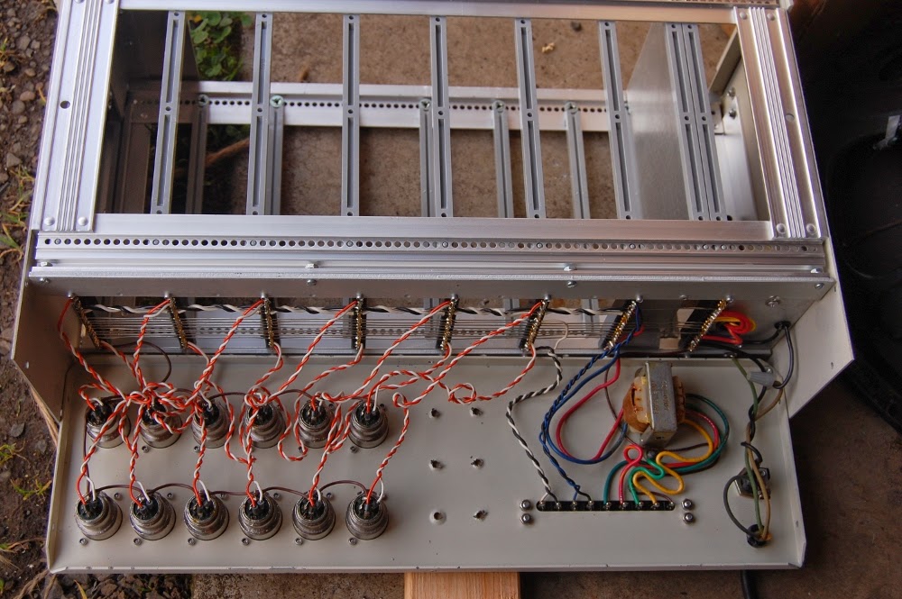
The original design is actually pretty cool. You have a case ground (black) a high impedance (blue) and a transformer coupled low impedance pair (orange/yellow), so you could cable select impedance. Reminds me of the old SM-57 transformer bypass mod, just so happens to be BUILT IN and optional on these.

That said, sourcing the 4 pin connectors for it now is something of a nuisance, and I want to reach for the low-Z mode anyway, so what you're about to see is an easily reversible disconnect of the high impedance (pre transformer) circuit.

Form factor is identical, I happened to have a couple three pin Cannon male inserts lying around, which turned this into a full "bolt on" mod.

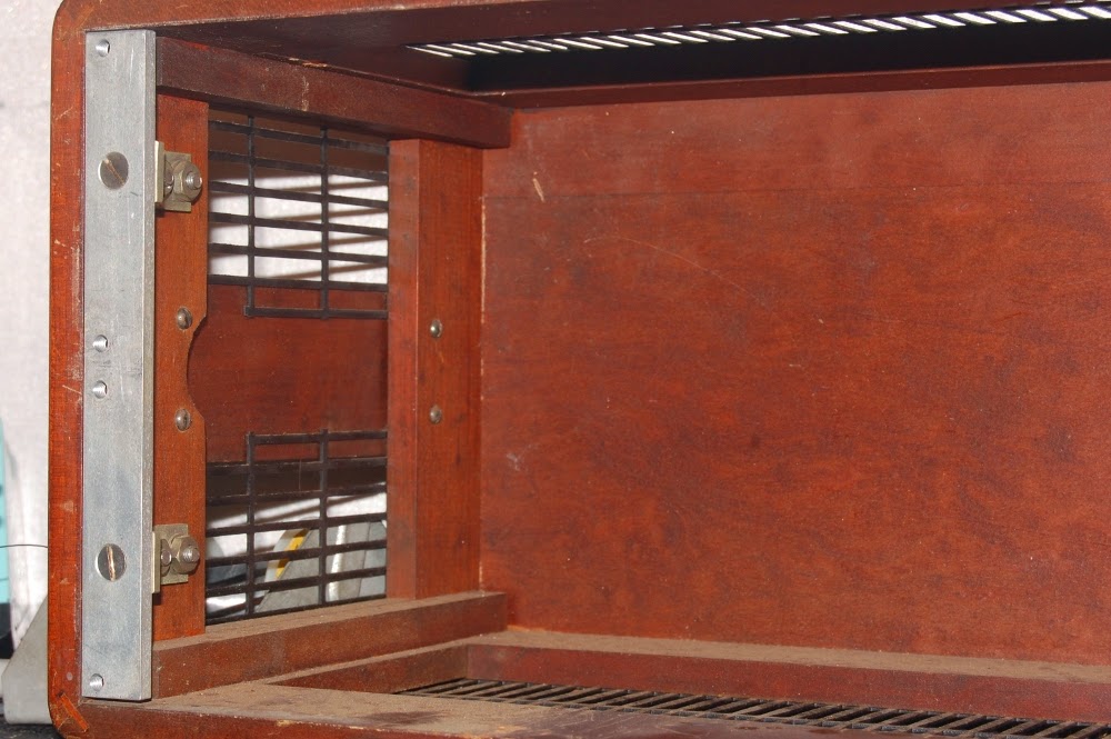
The dirt and crud even lend a period correct feel to these, so as not to bum out the vintage zombies. I jest, partially.

So a bit of heat shrink on the blue hi-Z feed, connect chassis to 1, and I decided to jam orange as "hot" on pin 2 because it's a "warmer" color than yellow. Completely scientific like. Whatever. The mic works, I like the sound, it will get used.

Apologies, I don't seem to have taken a picture of the completed unit. It looks like the connector end of a standard microphone, my guess is that if that isn't explanation enough, this mod might not be for you.

Friday, April 11, 2014

Drilled out the rivets securing the back panel of the IRP Voicematic to allow a bit of useful modification.

It's a little difficult to discern here, but there's an uninsulated wire in between the black and white twisted pair along the backplane buss. According to my scope, the bare wire is the audio feed line from the independent cards to the master summing section. Visible are my sloppily hand aligned holes.

The idea here is that since all the cards output direct to this buss wire, I can get away with installing interrupting jacks (Switchcraft 12A) so that the card feeds the tip directly, which is shunted to the combined buss when nothing is plugged into the jack. I've opted to only go so far as metal work on the 11/12 hole, as I don't have a card for that pair. So yeah, I'm leaving a HOLE in the case. Never know when it might come in handy.

Functional, though the recovery amplifier provides for considerable gain, so direct patching the two input card has a much lower level than what is available at transformer output. I guess that's what booster pedals are for.. HAHA.

Wednesday, April 09, 2014

Here are some more shots of the woodwork on the TIC 500 set (both of which are now recapped, and to varying degrees functional).

Assembly details, fairly apparent.

Precision.

Each unit is self powered, the large bodied grounded plug assembly just fits through this hole necessitating a keyway for other cord.

Another peek at woodwork, only one side is drilled like this..

..which makes for a nice view.

Though to be fair, the ample ventilation provides for largely unrestricted observation.

I found service data! TIC was evidently acquired by Acton Labs in the mid 1950s (or thereabouts), and in reading this thread it would seem TIC was H.H. Scott's company after departing GenRad? http://antiqueradios.com/forums/viewtopic.php?f=8&t=221316
Regardless, I'm happy to have a roadmap I can follow should I decide to tackle the motorboating issues. I'm somewhat on the fence about that, because of an interactive response to signal that nudges these into musical instrument territory.