Thursday, January 26, 2012

Removed my Webster 288-1 wire recorder from less than optimal storage conditions yesterday.

Electronic Memory?

No. Magnetic Media.. ..let's take a closer look at that, shall we?

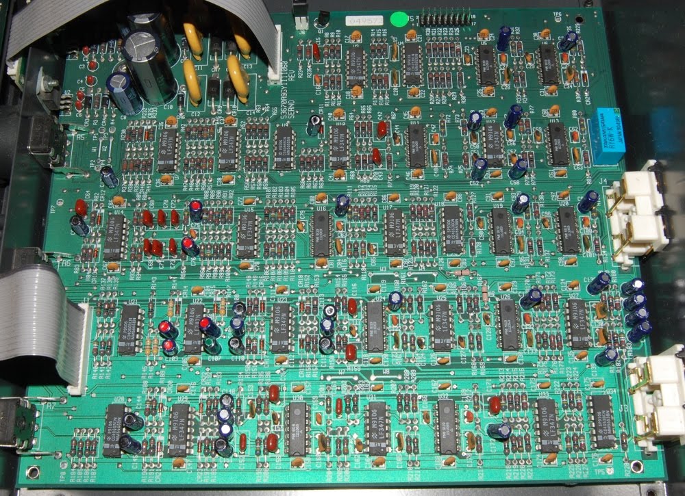
A ferrous thread, upon which resides the imprint of brute force magnetics. Granted, there are supporting electronics involved, but given our current vantage point in regards to technology this device seems a few generations removed from "Electronic Memory". I wonder what form our current technical parlance would take, had this use of words stuck.

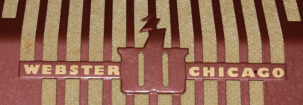
Beautiful logo. I can't fault the machine or designers (or, as is more probable the case: marketing) for such goofy use of terminology. It adds to the charm.

Input is a three pin Beau / Cinch-Jones connector.

Today was the first time I've seen reference to Beau in regards to the classic Cinch-Jones plug configuration. I approve. Looks like a recent company, hopefully they will support and provide all manner of "antiquated" connectors.

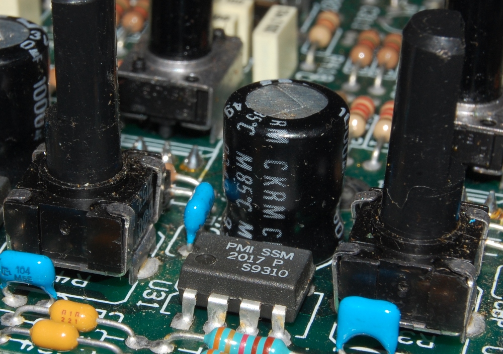
I was quite apprehensive about cracking the closed case after retrieving this from a humid environment, thankfully it would appear as if adverse effects were somewhat minimal. This moldy looking splotch bears the outline of the knobs for good reason, that point is situated in very close proximity to the bakelite knob. A few thoughts spring to mind: Perhaps as the organic elements of the material decompose an outgassing of molecular nutrients is deposited on nearby surfaces, establishing a rich base upon which mold grows. Perhaps the mark is a build up of deposits of the vapor itself. Or maybe it is mold and just prefers to grow where air movement is minimized. I'm still considering the mold theory suspect, I believe this is a very early stage of the white film problem I spoke of here.

Eh, I'll be happy if it cleans up and doesn't return now that the Webster is safely back to climate control.

Monday, January 23, 2012

Spent more time in organizing the studio space over the weekend than in working on stuff. Pretty sure the every other day post cycle is going to fall apart.. will continue with a more natural schedule.

Replaced all the lamps in the AC-8. Found the octal case I plan on using for the T4 build. Discovered the brakes need a going over in the fastback.

A bit thin on content today, getting a rolling start on the week.

Saturday, January 21, 2012

Gave the Fender MX 5216 a quick run through, cleaning switches, as they were acting dodgy and this unit may be rotating out into a new home.

Working surface, after I'd dropped the PCB off each sub-section. While I had open metal, I took the opportunity to wipe it off.

Original buildup.

Each sub-section houses a horizontal circuit board with duplicate circuits, lots of ribbon cable.

Everything is pretty easy to get at, and through hole construction. Built in the mid 1990s, when miniaturization was really getting a toehold.

I'm guessing this could benefit from a recap. I'm not tackling that one right now, but at 10 caps a channel it doesn't look too terrible even if the pots outline an obstacle course.

Per channel breakdown: first stage is a SSM2017, TL072 is seated in the EQ section, NE5532 in the Aux send section, MC14053B in the output routing section and an NE5532 acts as post fader recovery. The summing section is populated almost entirely with NE5532.

When I bought this in ~2007, two of the input channels were non functional. As it happens, the input trim control pots had popped apart, it was a matter of realigning and tensioning the metal legs to hold it together.

One of the ribbon connectors popped free unlabelled, and since several of the header connectors at the board are not populated, I had to reverse engineer the connection. Reading continuity at Aux send 1 & 2, it became reasonable to conclude it belonged at the Aux send 1 & 2 block.

Thursday, January 19, 2012

My favorite discovery in the last 48 hours is the use of layers.

Previously, I spoke of thousands of clicks, shooting off into mesmerization. Layers would have robbed me of the insight, and I suppose now I will have to pursue some other automaton type task when I feel the need to hit the reset button of my mind (MIDI sequencing in step edit does fill in nicely). It boils down to this: I can build a framework of grid lines (depicted here in cyan) upon which to reference the drawing, and when I'm done: *poof*! Deleted. Instead of whittled away over hours.

This triangulated grid was deployed due to the fact that the part has no parallel straight lines. It's easiest to find center this way anyway.

Just the click of a button. Delightful!

Tuesday, January 17, 2012

CAD is the new video game

The last couple coffee fuelled morning ramp ups have been spent on sheer repetition in QCad.

How many thousands of clicks did it take to go from the above to below? Even Ruk doesn't know.

I find a satisfaction in doing a repetitive task like this, once the action becomes automatic the mind will drift along lateral channels. So, while I am pretty sure there is probably a far more efficient way to go about drafting the finished drawing I'm not entirely sure it would come without detriments. Of course, I say this without the burden of carpal tunnel..

The polylith, it's coming to get you! A side effect of said mental drift (benefit, if you will) is it makes me somewhat loopy; paving way to associating the above part detail with a grip of cycloptic granite monoliths looming on the horizon.

Of course, moving the drawing around produces Moire effects (simulated here through resizing the image in GIMP) which stacks a Mesmer layer on the entire process, further amplifying my feelings of being a happy worker.

Serious word of advice: when drafting in CAD, partially sacrificial lines (that is, lines from which you will be trimming an end) should be drawn to exact dimension whenever possible, because trimming something like 0.063379268 of an inch off of 200 lines is pushing the envelope on meditative satisfaction..

Sunday, January 15, 2012

And now, it's time to clean pots & switches.

Patchbays are wired up, 1-4 stereo XLR on A bank (channel 5 pair is just dummy infill at the moment, we can credit laziness for this), and 1-8 stereo pair of 1/4" on B bank. Audition and Program output are fed to the right end of the patchbay, Program output being normalled to the amplifier input (and still available at the XLR output when something is front panel patched into the amplifier).

20 four conductor shielded wires. Shield is connected at the mixer end only and one conductor is unused in the XLR feeds which require one cable per connector. The 1/4" feeds utilize all conductors for the stereo pair per wire.

I misplaced channel 6B in this shot, it is wired on the A bank. The vertical "columns" are similar, for example: farthest left is A channel LEFT, the A channel RIGHT, then B channel LEFT and B channel RIGHT, etc.. Terminals within the tabs are from "top" down: signal hot (+/-), signal neutral (C) and ground (S), the characters in parenthesis being call-outs in the Autogram AC-8 manual (Common and Shield).

When I originally wired up a few XLR to try this thing out, I was scrounging up crimp connectors from my parts boxes. Pictured here is a connector type that became the bane of this installation: the closed ring, which requires the complete removal of the terminal screw. I also wound up trimming off the insulation after the first two. My advice is if you're going to wire one of these up, do it with uninsulated fork type connectors, a thousand times more pleasant to work with.

I should also mention that these boards are set up for pretty high level signal (rated at +8 dBm nominal, with a +24 dBm headroom cap) while most studio gear is +4 dBu, so actual results of mixing may be fraught with complication (higher noise levels than preferred). My application is to drive the inputs off other mixing desks which will shoot my signal a bit closer to being in nominal range, having driven the channels last night direct with an EMU Morpheus synthesizer I wasn't getting deflection of meters. The Autogram (and really, any radio mixer, especially when all input modules have been set up as passive transformers) needs to be fed healthy levels of juice.

Friday, January 13, 2012

Somewhere, along the timeline of human history, Friday the 13th acquired a bad rap. I've decided to celebrate this periodic calendar event with pictures of broken stuff.

Cut short, in their prime.

I tacked on the mood lit AC-8 not because it is broken (superstitiously touches wood.. hahaha) but as a counter balance to the sorry tubes above. I also need to dig up four more bayonet mount 30 volt miniature lamps.

Such subservience to superstition illustrates the fact that by and large, we are all essentially overgrown children. I dream of a day in which a critical ratio of the population breaks out of that stifling shell and we can move toward self sufficiency and betterment in a reasonably intelligent world. You know, let's start scratching the surface of our potential as a life form...

But it's an uphill battle, and we're losing ground. I present this lawsuit as an example of why we can't have nice stuff and the human species is really looking more or less doomed every day, Friday the 13th or no. While it is unfortunate someone is burdened with crippling problems, wildly shooting into a crowd with the intent of picking off beneficial entities is reckless and absurd. Uphill battle indeed.

Apologies for polluting my thread with social commentary, been fighting a head cold this week and am surly and gloomy. Happy Friday!

Wednesday, January 11, 2012

Still not as far along on the wiring process as I would like, but, if I had my way I'd be able to invest all day on my projects as opposed to nibbles in the pre & post job moments. Here's a half way update to meet my self imposed 48 hour cycle...

The Autogram AC-8 base sits flush to the desk/shelf on which it's set, the idea is the wiring passes through a hole routed in the desk, which isn't an option for me. The answer? Feet. Beautiful scrap from my good friends at One Drop Design makes for serviceable elevation required to pass a loom of cables underneath the mixer.

Unfortunately, the base is bent metal, so only the front of the mixer offers the screw in option (unmodified)..

..as a result, I simply placed more yo-yo halves to the rear of the mixer loose. Yes, I deployed the pink ones in that application.

Moving on to my 1/4" input bank, I'm installing a hard wired rear patch bay of aged Switchcraft jacks. While the holes depicted are not from the panel I'm installing, they do pose a concern over using older gear.

Never one to bow to the newer is better philosophy let's show those jacks who's boss. Pictured here is a 22 gauge cleaning brush chocked into the bit of my cordless drill.

Improvement. I will probably have to give it another pass with contact cleaner (this one was done dry)..

..but first I may need to rethink my choice of tools.

Dymo labelling, giving the appearance of completion (only the lower panel is actually soldered up). Onward and upward...

Monday, January 09, 2012

Since I'm not wired complete yet on the Autogram, we're taking a quick detour.

Stereo imaging processors have captivated me, to some degree, for years. While I haven't courted obsession and sought to buy up each variant I can find, stereo imaging hardware, like drum machines, are something I have a hard time passing up. Here is the Omnisonix, Ltd. 801 Omnisonic Imager, hailing from the first stretch of the 1980's (so far as I can tell).

Overall a pretty simple device, ins and outs and an on/off switch. Let's have a closer look at that statement printed on the back..

Well. Damn. Mind you, I do like utilizing this sort of thing on stuff now and then, though to be fair, what it offers in width it subtracts in depth. It would appear I am free to use this as an effect after all: legal status of Omnisonic Imager

Let's crack it open and look inside. The wood side panels were not visibly connected with anything from the outside.

After a bit of gingerly bending and squeezing, we have this. The secret sauce is evidently contained within that red polymer block.

The secrets, they must be profound. It's funny, I have a completely passive stereo expander that is very similar in appearance (sans the supporting electronics, naturally). My guess leans on there being a phase inversion stage for each side that is "added" to the other channel, effectively subtracting the right from the left and vice versa. This could be achieved with transformers (in the case of the passive) or by op-amps (and on and on) if you have the luxury of power.

The red block can be seen through this PCB, at about the 50% - 75% (L to R) point. I count seven points in which it connects to the PCB. Three for common referenced bipolar power supply, two for right and left input and two for right and left output.

So as not to give the impression that these were all primitive gewgaws, here's a Hughes AK-100, from the minds (well, one mind, according to this article) of Hughes Aircraft, the same Hughes Aircraft that spawned the Spruce Goose. The SRS function seen on many a small boom-box type stereo is based on the Sound Retrieval System that this unit is built upon.

I'd like to take this moment to point out that simple is not always superior in the far reaching cryptic chase of ever elusive tone.

All processors take some to give some, and are usually best used sparingly (unless, well, you know...). Stereo spread manipulation (not monophonic placement in the stereo field) seems one of those uncommon tools, which seems odd to me, since it's been the better part of a century since Blumlein cut the advancing ground on stereo sound, long before we were gifted with the crunchiness of abused amplifiers.

Saturday, January 07, 2012

Aluminum (or aluminium, if you prefer) is a sticky metal.

This splash is what's left after a plunge up to 7/16ths with a stepped bit (or unibit, if you prefer).

The bit itself also suffered some adhesion issues, I had to pick metal from between the flutes between each pass. My goal here was to overbore a hole for the 3/8" shaft of the chassis punch, which allowed for a little shifting room to align the punch independent of actual drilled hole (my press having a few issues that I may get around to addressing).

Enter into the equation the chassis punch. Photo sequence here is going to sidetrack into another hole making session (as evidenced by the existence of steel in lieu of aluminium).

During that previous punching session, I needed to punch a one inch hole for an admittedly large pilot light assembly I am installing on a slave amplifier build. So, naturally I grab the punch set labelled 1" and move on. Sadly, it would appear as if my "vintage" chassis punch set of Japanese manufacture was prescribed to the metric inch, as my panel mount lamp would not fit the hole, which measured out 2% shy of an actual inch.

Thankfully my hand operated filing operation didn't need to ream out an actual inch.

The process was a pain in the ass none the less. This is also the time to point out that sometimes alignment on center of parts is inferior to unified distance of space between finished assemblies. For the record, that fuse assembly has been usurped by a superior one, and I do acknowledge there is a trace of rust on that power switch - electrical function will be assured prior to implementation.

Back to the 1U XLR breakout connector panel for the Autogram AC-8 (amongst other things), as it turns out, the snug inch hole is roomy for Switchcraft panel mount female XLR jacks (I have taken to measuring everything prior to commiting work). There is, in fact, enough slop to align the actual parts to compensate for drift that occurred in the punching phase. And so..

..it was made. Hole explanation from left to right: stereo pair XLR male send, 5 stereo pair female XLR input, one speaker bypass switch to allow capacitor discharge through 22 ohm resistors as opposed to my studio monitors (I live in a manual world). I'll update with a finished shot once it's finished & functioning.