Sunday, June 16, 2013

After breaking the old Japanese chassis punch set I've had for ten some odd years, I figured I'd have a stab at cheaping out with Harbor Freight to see if I can find something serviceable. Took a gamble with a 91201 ten piece punch set. Something to keep in mind about this set, it is designed around outside diameter of conduit. Allow me to demonstrate:

0.5 inch.

0.75 inch.

1 inch.

1.25 inch.

Working into space constraints, I really need a 1 inch hole, going over by 84 mils will put me into breaking sidewall territory, so I grabbed the 0.8835 "1/2" incher with the intent of making up the difference with file by hand. To its credit, it did seem to make a bit more progress before failure.

There are a lot of ways to botch a screw, and I've sheared my share of hardware via the mechanical force of the hardware itself; I do not recall seeing something quite this bad.

A little internet sleuthing (admittedly done BEFORE I purchased the tool, so you're all encouraged to laugh heartily AT me) indicates a lot of failure with the small stud, but apparently there's a newer revision that addresses the problem. Hopefully mine is first rev, this level of failure indicates process issue with me.

If you're bored and want to read more about this sort of thing, look up "cast iron railroad bridges".

Brittle metal.

I've given the stud a bit of scrutiny, and cannot find evidence of material having fractured out of the screw. Thread count matches, and I can see where faces would line up. However, the metal is now highly deformed and the gap will not close when lined up, as if it was under heavy preload prior to failure and relaxed into a state that puts a wide void where thread should be.

It's almost as if it's laughing at me.

The panel is getting nicely chewed up at this point.

Side by side, a comparison of losers. Really though, it's pull stud failure on both accounts, so instead of fussing about with further stupidity I'm thinking of visiting my local reputable hardware supplier and seeing what I can get in the way of threaded stock that can support this sort of load.

In the mean time, for this one, I just drilled it out as high as I can go with a drill (0.875") and made the rest up with a hand file, as evidenced by the bought of scraping situated inboard of the abnormally large pilot lamp assembly.

Now that the front panel can support a mock up, I'm free to position the iron for plunging the mounting holes and then moving on to tube socket & various. Thankfully, I'm substituting a 6BQ5 for the 6K6, and I can get away with making a hole to accept 9 pin miniature with the drill press. Otherwise, I'd probably be a bit irate about this experience.

Also, FWIW, my snap edge is the one pictured on the left, the uglier cut to right being one conducted in field with a circular saw (by others). Thought it crucial to defend my work since that will all be buried in woodwork anyway. HAH

Saturday, June 15, 2013

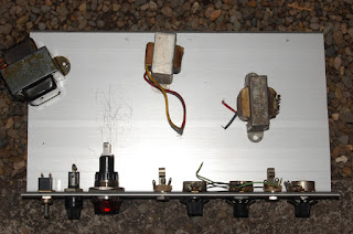
Set about building a loose Fender 6G15 clone today. Then I got the wise idea of deploying an oversize pilot lamp assembly on the front panel.

Sometimes good ideas end in tears.

Clearly there wasn't a whole lot of steel connecting the threaded draw stud and the die assembly, I was having a hell of a time pushing the punch through (bending metal was involved). Apparently 8 gauge alumin(i)um is beyond the capacity of this instrument. The instrument in question being a "vintage" (it has a wooden box, no idea on era of manufacture) multi punch set of Japanese manufacture.

I also felt a little elation at rediscovering the root of the word "borked", typographical error in my naming of the file "broken-punch". Sure, this may be in error, but I'm going to demand you allow me this silver lining and refrain from dashing my bit of feel good until you see a pic of the finished panel, thanks!

So close. I figured I was at about the initial shearing point where actual force involved drops dramatically, which was good, as this was proving to be a PITA to punch by hand. Then the force required to turn the screw dropped like a rock.

Well, I've got an idea of where the hole *should* be.

Pretty sure this won't accept the 1 inch lamp body though.

In other news, the scroll saw handles 1/8th inch 6061 (I think) just fine with a 10 tpi (Delta 40-193) regular tooth blade. I went super easy on the feed rate, and ran into no problems. I'll be having a go at using the chop saw as soon as I find a sacrificial 10 inch blade (not my fine finish framing blade).

I did flinch a little at running completely through, but scored as such and with a quick swipe of hacksaw (before deciding to give the brute force method a go) the material snapped pretty well. This is where the metallurgists may pile in and inform me the 6061 is wrong. The extrusion is surplus from seismic joint assemblies, it's either 6063 T5, T6 or T52; 6061 T5, T6 or T51; 6105 T5 or T6, 6005 T5, 6005A T5 or T61, according to current manufacturer datasheets. Anyway, I've got plenty for now, it's nice and thick, and will be turned into stuff that is not part of a building.

In the end, I think this oversized pilot lamp will be worth the effort and headache. In the meantime, in looking at the going rate of Greenlee punches (taking into account the variety of sizes I need) I'm thinking the path of least resistance is to fix my welder, fix this punch and tough it out until I finally get around to completing the CNC build (Couple years? Sooner? Later? Time will tell, taking bets now... ).

Monday, June 03, 2013

It's high time I commence working on enclosures. To assist in this endeavour is a new to me Craftsman 103-23100 benchtop drill press that evidently hasn't seen much use in a while. This is replacing a Harbor Freight special that essentially boiled down to a nightmare of radial slop. I could plunge a neater line by hand, but I digress.

I'd much rather talk about stylized mid century domestic US steel than the resulting product of decades worth of exponential bean counting. Make no mistake, it may be manufactured in China, but those cheap tools are American products. Apologies, that's just my Monday morning cheer shining through.

The prerequisite visual inspection indicates a little work is in order. While the angle of shot does not reveal it well, I can report that both legs of the early cloth covered AC mains wire have slipped their insulation at this point.

I think the motor is not original, the bolts however may be.

I'll make sure to evenly distribute those washers upon reassembly..

Removal of the AC access plate indicates some years of use as a wood working tool.

Not high tech, but the installation outlasted the wire itself.

There's a little black smudging on the soldered joint about an inch back from the stud, I'd like to know what's been going on here before putting the motor back into service.

The corresponding point in the wire...

...supports the theory that the insulation failure coupled with a conductive path of oily wood dust provided a high resistance path that could heat up with use. Or, perhaps it's just an oily spot. Either way, the motor is functional and intact. My elation at having an operational piece of equipment is evidenced by the fact that I clearly leaned forward a sixteenth of an inch while taking that photograph.

New wire snaked into place, now with a chassis ground.

While operational, I think I may have to dig into this one deeper, as the rotational assembly seems to exhibit more resistance than I would like, while the vertical travel is as lubricated as a ■■■■■■ ■■■■■ and will drop the drill via gravity feed unless I adjust tension to the point where I can no longer gauge the feel of the drill.