I have however done some wiring loom work on the Autogram console, cueing things up for a bit of recording. This involved use of some 24 ga four conductor plus shield wire and crimped connections, the crimp connectors are designed for a larger wire so my process just barely squeaks by my established quality control to merit inclusion here.

Tool set is pretty simple, a less than pristine (car toolbox ripened) Channellock 909 crimping tool and red insulation connectors.

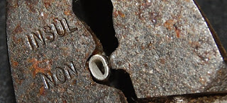
I start with the connector situated such, sans wire as this a prep step.

Gentle pressure to the point of distortion, the goal here is not to let the eye hole collapse as it still needs to receive wire. The connector is crushed to the point at which relaxing pressure on the tool will allow the crimp connector to be removed easily from the plastic insulation jacket.

The wire is stripped to roughly the length of the crimp housing. I try and strip it a bit shy as the finished result will look neater.

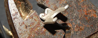
Gently positioning the connector in the jaws with the nipple at the seam, wire is threaded centrally..

..and the first stage crimp is executed with a nominally firm squeeze.

Please overlook my poor placement of depth of field in the photograph. This used to be the stopping point for me, though I would position wire to one side as the gap caused by the seam isn't the most structurally sound point to lay wires.

The connector is then returned to the "insulated" slot in the jaws and truly crushed.

Done.

These are XLR feed balanced inputs, I connected the shield separately to the body of the connector and doubled it up with the ground feed on the chassis connection at the mixer. Probably needless complexity, but I figured it may come in handy in event of ground loop troubleshooting should the need ever arise.
No comments:
Post a Comment