The amp had been red-plating. As it turns out, this 150K dropping resistor (the bias supply is fed from the full high voltage B+ secondary, knocked down and separately rectified) had drifted up to 234K, and the 15K between cathodes of the bias smoothing capacitors had been replaced with a 45K flame proof, effectively tamping the available bias voltage down to useless levels. Hence, a bit too much current flow through the tubes.
Since this amp is purposed to be a player, and is already far from pristine, I'm comfortable with performing non-reversible modifications on it. To facilitate an adjustable per tube bias tap I undid the original bias feed at output tube grids (the connection above the nut) and removed the two 220K resistors. Full bias is now delivered from the adjustment pot to pin 1 of output tube and a 270K half watt carbon film resistor connects pin 1 (G3) to pin 5 (G1).
I also plucked the 1K5 grid resistors flanking the yellow 0.1 @ 600 coupling caps. As you may remember, I had questioned the lop sided approach to the inner and outer pairs of output tubes. I figure this is as good a place as any to test the effects of resistor distortion, so I planted 1/4 watt 1K6 carbon comps on every output tube signal grid. I realize there's negligible DC drop at this point, but I had the resistors on hand, so...
In order to minimize the flying parts construction, this modification entailed physically switching the alignment of signal path at the post phase inverter coupling caps seen here. Since I had already gutted everything on the "upper" row, switch over was easy. This move the DC bearing phase inverted signal back over the circuit, but the AC feed to the output section is a straight shot as opposed to incredibly long flying leads. So, I'm cautiously optimistic that I haven't destabilized the amplifier do to messing with lead dress (and I'll know where to start looking if instability is a problem).
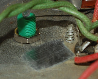
I did have to create another chassis ground connection, the preparation of which involved removing patina with hardened steel (a chunk of razor blade). Metallic dust was removed by magnet. I took some close up pictures, but the razor thin depth of field didn't do me any favors. So those pics are not included.
One 100 watt soldering iron later.
Here's a sidelong shot of the modified output section before I reconnected the feedback tap at output. 2 watt 560 ohm screen resistors were also added, this is on top of 1K drop on the screen supply, which may be adjusted depending on performance seeing as how the 1K is made up of two 500 ohm in series.
The white cloth wire connects tube cathode to test point, which is connected to ground via a 1 ohm resistor.
I've done uglier work. I'm not elated about the aesthetic appearance of the screen buss (upper yellow wire) and the eyelet connections ofr the bias supply are a bit congested with the trunks of red & white wires, but over all there remains room to work and everything is electrically sound.
Another angle on the same stuff.
Over all guts. The ten footer view isn't half bad. I'd like to belt the three Sprague Atoms on the left down, but construction grade double stick tape will have to work for now (they've not given me any problems).
In order to give AC mains and the body of one of the 10K pots a comfortable berth, I had to rotate the fuse holder. Since the chassis is punched with a D hole, this entailed a pass with the file. The scuffs on the rear panel being a typical rookie mistake (I'm embracing the scratch & dent look on this amp) moving along...
Here's the finished set up. I slapped in a matching set of 10K pots since the picture of the mock up (THANKS DAN!). However, I haven't yet had the opportunity to test this, since my benchtop variac suddenly has a failed outlet and the other variac at hand has an intermittent short that was swinging the ammeter once it hit 50 volts.
So yeah, I expect some more variac discussion on the horizon.


4 comments:
Love the chassis solder glob. Was that 100 watter a big giant Weller from the old days?
Sorry to hear of your variac probs. I do have one of yours here. I could drop it by tomorrow if you like.
It will be way boss to get that old Traynor breathing fire again.
If by old days you mean big Weller W100, then yes - if you mean one of the huge jobbers with a wooden handle, then... no. Frankly, I'm a bit afraid to use those (and they are too ungainly to dodge wires, yeah, that's it).
Got sidetracked today and haven't resolved the variac puzzle, so if you're in the neighborhood I'd be happy to give it a rip, no need to make a special trip though.
Wouldn't those fragile harmonics benefit from another stage of gain????
Nice work taming the Red Plate Express.
Another gain stage is in the works, I just want to get the amp as dialed in as I can as-is before exploring that territory.
Post a Comment