
It would appear that mine is an early version of transition from 7027 to 6CA7. Parts date to early 1969.

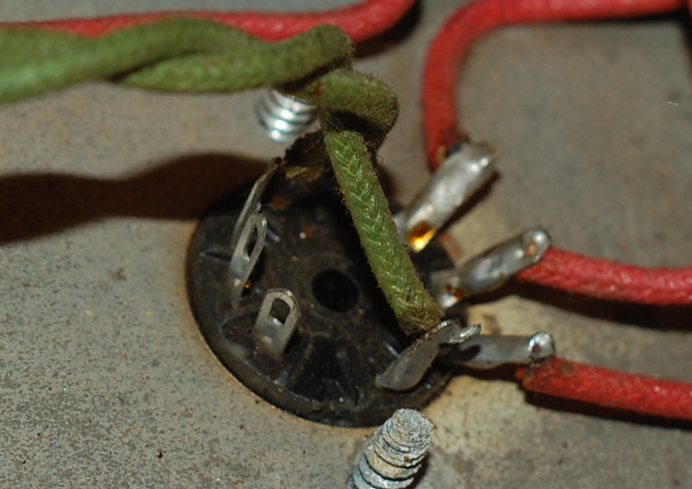
In thumbing through online pictures of YBA3 guts I have not seen this, but short of carbon dating the solder it really looks original to me. I added the knob since I like non conductive stuff to grab hold of when faced with amp guts. The mystery was what function this pot served, since it has nothing to do with the bias section..

Above is the first (or earliest I can find) revision circuit amplifier: non master volume, choke in the power supply, fixed resistor bias and 7027 output tubes. The aforementioned 892K mystery pot is high lighted in red, the 68K & 470 ohm resistors tied directly to the wiper. The only other real departure this amp has from the above schematic is in blue, as in that part can be omitted in its entirety and the following output section is referenced.

I elected to mark up a later schematic in lieu of the early 6CA7/EL34 circuit due to the cleaner scan (sadly my amp does not have its own schematic in the lid), the primary difference between the earlier and later sections are R51 & 52 - high lighted in red, those 1K5 grid resistors are not and never have been in this amp, however the matching (green) 1K5 feeding the grid of the "secondary" (outer) pair of output tubes IS in place (as seen on earlier schematic).
Also unique to the outermost tubes of the PP quartet is a 47 ohm 2 watt screen resistor (inner green). I'd been scratching my head about this, wondering why the circuit is different between the inner and outer pairs of output tubes when it dawned on me that the grid resistor might shed enough negative bias that the screen resistor is necessary to retain over all balance?
That line of inquiry is somewhat moot. I'm going to be installing screen grid resistors on each and every output tube. In addition to the grid resistors I plan on installing individual bias branches per tube (replacing the yellow stretch & pulling the bias supply feeding pin 1) with banana access to 1 ohm cathode resistors.
Orange overvoltage protection circuit has been removed, though I would consider replacing it if I had the correct parts.
Blue output section places speaker loads in series. I'm thinking of changing this to a standard parallel wiring.
There's also the little matter of an open triode to exploit.
3 comments:
A free half of a pre-amp tube? They couldn't find a use for that in 1969?
The obvious answer is to hotrod the thing with an extra (switchable?) gain stage.
Agreed, I've got to do SOMETHING with that. Can't let it go to waste.
I have a YBA 3 with an original schematic on the lid.
It the wiring in the amp was changed and I couldnt figure out how or why until I read your post. Thanks
Post a Comment