Tuesday, November 30, 2010

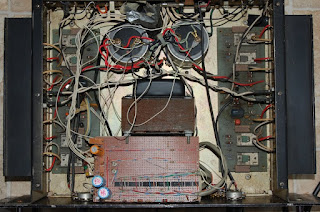
Another variac/variable DC supply for the bench, this one shows the mark of DIY so I figure I should check it out before using it.


We have no need of sleek, streamlined bullshit here.


I begin to wonder if this wasn't completely thrown together by someone, as the 200 VA 24 volt step down transformer (in black) and and huge choke are designed to carry current far in excess of what the 2.25 amp autotransformer can deliver (2.25 amps being its design limit no matter what voltage it delivers).


The rectifier for the DC side illustrates gargantuan over design..


..while the profusion of electrical tape and some of the taps illustrate haste. This thing is certainly a cobbler hammered out on some freaks workbench, should be right at home once I dress the bare wires and introduce it to some compressed air.


Here's a nice hook-up diagram for a variable autotransformer. Wall voltage is wired across either 1 and 2 (allowing a 0-120 volt range) or 1 and 4 (allowing a step up to 0-132 volt range) actual voltages are going to hinge what you have at the wall, the 1-2 = 100% and 1-4 = 110%. Output is at terminal #3 (variable hot) and terminal #1 (neutral).


Here's a shot of the markings on the choke, mainly because I like the distortions incurred by taking a shot through the perforated steel.

Sunday, November 28, 2010

This particular piece holds a dear place in the sentimental recesses of my mind. In the mid 1990s the shop sold this Fostex 260 to a Jamaican man, a few months later he returned claiming it was broken and he wanted his money back. The ensuing conversation was one of those instances when I wish I had been wired for sound and recording the proceedings around me. The satisfaction of seeing my boss called a thieving swine by an irate Jamaican was magnificent, and "Eit was brooken frum teh geat gwo" was instantly forged into our vocabulary when any ailing piece of shit crossed the threshold into our domain. The actual back and forth between this man and my boss dragged out for close to a year as we tried to make the man happy within the confines of not giving his money back, good times.


After being deposited in the bad amp room, much neglect and dust did ensue.

After giving it the exterior once over I power it up and began functional tests. Guess what. It actually is broken. The tape transport does register commands, but goes "clack clack clack clack clack" instead of moving tape. I haven't yet bothered with pushing signal through the mixer portion, because LED are far less satisfying to watch than VU meters.

The mixing capability on this deck is pretty impressive for a four track, allowing for two independent stereo mixes (Main and Monitor) in addition to two mono Aux sends and sweepable frequencies on both Bass and Treble ranges.

While the marketing sticker on the face isn't quite as unscathed as that of the 250, the head is in similar condition.


I fudged my depth of field position a little bit, but the mirror finish of the head is evident.

Saturday, November 27, 2010

Forward momentum on the PA system has dwindled a bit, one week and counting. It's more or less sorted and ready to fall into place, I'll probably trickle photo essay on the amp stacks out for a while.

In other news, I've bowed to the compulsion of grabbing some ailing multi-tracks out of storage and see what I can do for them. This being a FAR cheaper way of going about an analog capture of rehearsals than open reel tape, which is forced by means of economics to be serious recording only (at least in my world).

Up today is a Fostex 250. I think this may be the first cassette multi-track offering by Fostex, though I cannot be sure. I believe this hails from 1981 or 2, and it's not one to be dropped on your foot. (edit: a sticker at the bottom places "date purchased" at 10-18-1984)


First visual indicates the knobs have been plucked, minor irritant. This deck was in the same salvage operation as the Heil 400 power amp discussed previously, so I'm not complaining.


Channel 3 VU isn't homing to zero, hopefully this is a simple mechanical fix. I did power the unit up and run signal through all four channels, at first only meter 2 registered. I proceeded to slam the channels a little one by one and got all meters to respond normally once they'd been pegged once. I'm still holding optimism that the electronics are more or less OK on this.

Transport only responds to FF and RW, play and stop are ignored. Since stop is ignored I'm thinking this may be oxidized crud at the switches and not failed rubber (if it hasn't failed yet it is surely ready to do so), record ready seems to function along with arming and disarming each track. So, logic appears responsive. I'm going to examine the rubber and see what I can do in terms of sourcing it (there's a heap of machines needing transport care, so you'll see a lot of disassembly before we find the mother lode of rubber bits to make us happy).


If the survival of a marketing sticker on the face of this didn't clue you in to the relative lack of wear this unit has seen, that head shot should. I'm hoping the gut shot we see once the case is cracked is just as pristine.

Monday, November 22, 2010

For high frequency compression drivers, I prefer tube power. Here's my EICO HF87 power amp, which will be seeing duty on the HF horns again this year.


Originating sometimes in the early 1960s, this was a kit build. As I recall (it's been over a decade), the builder assembled it wrong, tying B+ voltage to the filament line at the 12AX7 input. As a result the amp would shock people, and probably saw very little use. I received the amplifier in a speaker transaction, and rebuilt it.

A few years back an unlit candle toppled onto the powered up amplifier un-noticed, and proceeded to melt into a puddle of wax at the power tubes. After cleaning up the amp continued to operate fine, for a while. As it turns out, wax had infiltrated the socket itself and begun to pave the way for failure.


I don't think the candle that melted down was turquoise, so it appears that there's been some reactivity between the charged circuit and surrounding substrates over the wax bridge.


I doubled the size of the above shot in GIMP, a macro attachment is certainly on my future shopping list, along with a cage for an EICO HF87.


Octal sockets are pretty easy when it comes to remove and replace, and while a single socket is the main failure point, I'm going to replace them all for good measure.

Sunday, November 21, 2010

Less than two weeks to go, I've begun excavating the PA speakers. First off, I want to have a look at the bass bins, as this is the element of the system that gets the most abuse. I'm thinking of trying to get out of the habit of calling them subs, as it seems the more I put my head around the mathematics the less deep into true sub territory they go, that said, they are big, heavy, road worn and sound impressive enough that I can probably call them what I like and not meet much argument.


I've knocked this picture onto its side to adhere with my landscape aesthetic preference, so you can correct for gravity in your own mind. Obviously I've been using my speakers as storage for organ guts, which just adds to their charm.

I picked these up in Portland in +/- 2005, a quartet of empty cabinets. The seller claimed that these were the remaining four of a lot of 16 folded W horns built for Carlos Santana's sound company in the 1970s, accompanying him on a couple world tours. I've yet to see photographic evidence to validate that statement, but the notion remains interesting enough to share.


So yesterday I finally got around to making a proper attempt to map these out and calculate volume, that I may stand a little more chance in determining acoustical properties for the safe operation of drivers. Time will tell on the higher mathematics absorption front.


Here's a shot down the gullet, more or less the starting point for the low frequency wave front. The 0.5625 square foot (9x9 inch) throat offers a bit of compression loading on the 15 inch driver. Length of the horn is roughly 7 linear feet, terminating at 5.3281 square feet of mouth.

After assembling this more or less in scale drawing I've determined the volume of sealed enclosure (in blue) to be roughly 3.884 cubic feet.


Depth of horn at the speaker (red) is 9 inches, expanding to 12 inches at the orange split point and further expanding to 16.5 inches at yellow. Outside dimensions are 48x48x18 inches, for what it's worth.

This year I'm only bringing out two of these, one loaded with a McCauley 6242 and another loaded with an unknown Eminence speaker branded Carvin HE-15. Probably high pass at 40hz or so, unless I can determine that these cabinets don't unload until pushed deeper.

Wednesday, November 17, 2010

And now for something completely different.. LASER tubes.


I thought I'd take a few pictures of these before packing them up and slotting them onto the maybe/eventually shelf. Standard light bulb is there for scale.


My friend Don saved these from entering the nebulous void that is the electronics recycling industry and shot them my way. At first, being in the midst of processing my CNC project, I thought "LASER etching/cutting!"; but a little research led me to believe that deploying a HeNe laser to cut material would be a lot like entering a stationary steam engine into a road race. I know lasers have been employed for measurement in the past, so I justify my ownership through scientific interest and onto the shelf they go. Plus, they sound pleasant when struck.


I still envision a death ray blasting forth from this point, thanks Hollywood!

Tuesday, November 16, 2010

On advice from a forum member I fired the Soundcraftsmen RA7502 up minus the 5A transistor on the B channel, under instruction to avoid playing anything loud through it. The following pic is a long shutter shot, in dark while the LEDs went through their start cycle (protect LED is not lit once the amp is on line) then a bit of light on everything for a few remaining seconds.


Just sitting at idle there is evidence that the missing transistor on the B channel is throwing the PNP and NPN rails out of balance, as that heatsink is not cold to the touch. After about 10 minutes of idle Channel A shows an offset of 48.7 millivolts while the ailing channel shows 148.7. I don't see more than just one trim pot (which I take to be bias), and on this amp it's imperative I don't knock stuff out of whack. The class H ranges to a higher voltage supply when headroom on the standard supply is approached, so blindly tinkering invites a BBQ. This essentially means I'll be securing a copy of the service data and giving it a proper go-through before putting it to work. Low likelihood I'll be bringing this to ENF, which is fine as I plan to only bring half the PA anyway.

I've decided I'm going to replace all the actives in both sides of the amp with either the On-Semi MJ21193/94 or MJ21195/96 complementary pairs. The standard ratings run is very similar, identical in fact except the SOA (Safe Operating Area) of 2.5A,80V,1 second for the 93/94 and 3A,80V,1 second for the 95/96, the real departure from similarity is in comparing the curves.


I'm a bit out of my depth in terms of relating power transfer to acoustical properties, but for the moment I am favouring the softer transfer curves of the 95/96 pair, not to mention the higher SOA. If anyone has an ailing RA7502 they want to cut free for cheap I'd love to A/B the different pairs.

Monday, November 15, 2010

It would appear as if the Heil 400 lives.


Happily sitting at idle.


I grabbed a used toothbrush from my tool bin and used its somewhat rubbery handle to nudge the offset trimpot into as near a null condition as the trimmer would allow.


0.4 millivolts, I can live with this.

Sadly, I don't have enough dummy load (yet) to really fire this thing up and watch it work, nor have I speaker loaded or o-scoped this amp yet, but based on DC voltage measurements alone it appears to be functional. There's a repair tag hanging off the power cable stating "A channel out", which happens to be the channel that has been rebuilt in its entirety. I think it possible that in our communal music store hang-over we took that to mean that an unspecified channel was broken, and into the pile it went.

I'm having a difficult time locating much information about the amp on the net. It does not appear to be a Heil branded Phase Linear 400, as the Phase Linear PCBs look different. Nor is it an Ohmega 400, as the faceplate is different and evidently the Ohmega uses odd-ball output devices. This amp has MJ15003 outputs, which appear to be in production even today. So, if you're reading this and have hard data on this amplifier, please let me know.

Sunday, November 14, 2010

After giving the Heil 400 a going over and determining there were no shorted actives I fired it up. Channel A has a DC offset of only 3.3 millivolts, and original channel B is sitting at 64.6 millivolts. I'll see what I can do to null out B, but it's not bad at all for having been neglected for over a decade.


Next down the pile is a late 1970s Kustom X SPA. This one was retrofitted with an LED array to monitor power by someone sometime after 1986, I think they were a touch optimistic about available power levels though. I purchased this unit in working condition several years back, and have noticed a sharp degradation in sound quality when last used.


Gutshot reveals a minor layer of filth, probably my problem right there.

This amplifier is roughly less than half the power of the other two, so at best it would be a stand-by amp in case of failure. That said, I already have operational backup amps, so any work done on this one isn't cutting progress toward the upcoming show.


My plan here is to pull and wash both driver PCBs, since they have a silt layer beyond the capabilities of compressed air. It's really sitting on a lower priority tier than the other two amps, but I think a wash will be a fun write up so I introduce the amp here.


Handy work of a previous tech will complicate the extraction of the printed circuit boards, but the LED show in use is well worth the nuisance.


A nice touch this, goes a long ways toward letting me overlook the use of duct tape elsewhere in the amp.

Saturday, November 13, 2010

Next up in the solid state power amp crawl, a late 1970s Heil Sound 400. This beast is in unknown/untested condition. I seem to recall the previous owner saying something about a dead channel, but this was in the mid 1990s and I was but a music store clerk. After spending over a decade gathering dust in the dead gear room in the attic I was instructed to haul it away with everything else.


Take note! These knobs go to 12.


Nice wide open guts.


Channel A looks to have been replaced in the early/mid 1990s, from the 40th week of 1991 manufacturing date code on the transistors. Looks like this amp is somewhat lacking in the sort of protection scheme that saved the actives in the RA7502, this notion is further punctuated by the fact that the driver board appears to have been replaced in its entirety as well. I'm thinking someone held a BBQ here.


Channel B on the other hand appears to be original equipment, bearing the 39th week of 1978 build date on most of the transistors. The part at lower right paints an interesting picture:


I'm trying to figure out how, in normal use, someone could achieve this sort of arc. Sort of makes me wonder about the internal conditions of this part as well. I'll sniff around for any dead shorts on both power rails, then perhaps apply a little voltage and see what happens.

Friday, November 12, 2010

Eugene Noise Fest is right around the corner, and I've the intention of providing sound this year. This essentially equates to my window of procrastination coming to a close as I assess the pile of amps and consider my buried PA speakers. I have three weeks to get my shit together.


First up is a Soundcraftsmen RA7502 power amp. This unit would pull brownout levels of current off the wall for a split second and crowbar into protect mode, cycling through those two states every four seconds or so. I contacted a forum member on audiokarma.org who used to work on these Class H amps and described the symptoms. He stated that's usual behaviour for a shorted power transistor or drifted components in the protect circuit.


Here's what I take to be the audio stages hanging off the actual power stage, more or less freed up from the power supply section. Power amplifier stage as follows:


Turns out I have a cooked output transistor. Thankfully the protection scheme in these amps is fast enough that I only lost one active as opposed to the entire rail.


Now to determine if this is a Toshiba 2SB554 or a Toshiba 2SD424. Hmmmm

Thursday, November 11, 2010

Ground Control, we have a problem.


In June of 2009 I purchased an early Grass Instruments S4 on eBay, well aware that it was in operational disarray. The seller simply tossed the open chassis into a box full of peanuts and dropped it onto a loading dock. Less than ideal shipping aside, I think that the majority of problems with this unit actually stem from poor storage. Which is the only reason I can comprehend for the fluorescent tube shards I've had to pick from its somewhat tacky guts.


Another selenium stack awaiting surgery, I think this makes five awaiting passage over the bench.


However, the interesting puzzle is nested in the wire wound precision potentiometers.


The resistive element is severed, rendering the pot useless. I have another wire wound pot that was floating around a parts bin with the same mode of failure, easy to spot the weak point of the design. With this unit, seeing as how the failure is nearly at the end of the travel, I'll probably take the easy way out and bridge the gap. The break in the parts bin unit is more centralized, so I expect a bridge would deliver an audible step. I'll continue to contemplate my options on that one.

Friday, November 05, 2010

Another week with minimal actual work on the electronics front. Sadly, this seems to be the norm. So, in the meantime here's some gutshot of a Langevin AM301 discrete solid state mixer. As it stands, I have a stupid amount of mixers in my to-fix pile. This one is no exception.


As you can see in this pic, channel cards G & H are different from the rest. They've been modified for more gain at some point in this units history. My to-do list on this involves reproducing that mod on the rest of the cards, a recap and some front panel slider replacement. I've hunted for some faceplate photos of this unit, but nothing I've found meets my quality control, so I'll just have to post some exterior shots next time.

For the moment , here's a component side shot of a standard card, my apologies on the poor depth of field and flash washout in this photo, it is the best of the current bunch:


And a shot of the trace plane: